


8
S
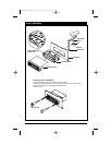
tep 1: The radio chassis is designed to be “Sleeve
Mounted” through a opening in the dashboard panel.
The required opening size is 182mm (7-3/16") x
84mm (3-5/16"). Cut or enlarged an opening in the
dashboard to accommodate the mounting sleeve.
Step 2: If you are replacing an existing factory
installed radio, an adapter harness might be avail-
able for your vehicle to eliminate the need for cut-
ting your factory wiring. Contact Radio Shack or
other car stereo installation centers for the availabil-
ity of a harness for your vehicle.
Step 3: Insert the mounting sleeve into the hole in
the dashboard. Bend the metal tabs on the sleeve to
secure the mounting sleeve to the dashboard.
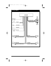
Step 4: Bring all wiring for the connection of the unit
(including the antenna) through the center of the
mounting sleeve. Connect the wiring as follows:
Yellow Wire (w/Fuse): Connect this wire to a con-
stant +12 volt power source (a power source that is
not controlled by the ignition key).
Red Wire: Connect this wire to a switched +12 volt
power source (a power source turned on and off by
the ignition key).
Blue Wire: Connect this wire to the (+) power
antenna activation circuit. If no power antenna
exists, tape-off the end of this wire to prevent short-
ing out the unit.
Black Wire: Connect this wire to the frame of the
vehicle (ground). This wire is the chassis grounding
wire for the unit.
White Wire: Connect this wire to the Left Front
Speaker (+) positive terminal or wire.
White Wire with Black Stripe: Connect this wire to the
Left Front Speaker (-) negative terminal or wire.
Gre
en Wire with Black Stripe: Connect this wire to the
Left Rear Speaker (-) negative terminal or wire.
Green Wire: Connect this wire to the Left Rear
Speaker (+) positive terminal or wire.
Gray Wire: Connect this wire to the Right Front
Speaker (+) positive terminal or wire.
Gra
y Wire with Black Stripe: Connect this wire to the
Right Front Speaker (-) negative terminal or wire.
Purple
Wire with Black Stripe: Connect this wire to the
Right Rear Speaker (-) negative terminal or wire.
Purple Wire: Connect this wire to the Right Rear
Speaker (+) positive terminal or wire.
Gray Cable with Red/White RCA Connectors:
Provides L/R Channel audio signal output to an
additional amplifier.
Note: This unit is designed to connect to (4) four
speakers. If the installation only requires (2) two
speakers, use the White and Gray wire sets to con-
nect the speakers.
Installation Procedure
WARNING!
Any wires left unconnected must be taped-off
or capped off to prevent shorting.
DO NOT connect speaker ground wires together.
DO NOT connect speaker ground wires to the
chassis of the vehicle.
DO NOT connect front and rear speaker wires
together.
FAILURE TO FOLLOW ANY OF THESE WARN-
INGS WILL RESULT IN DAMAGE TO THIS
UNIT AND VOIDS THE WARRANTY.
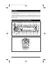
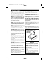
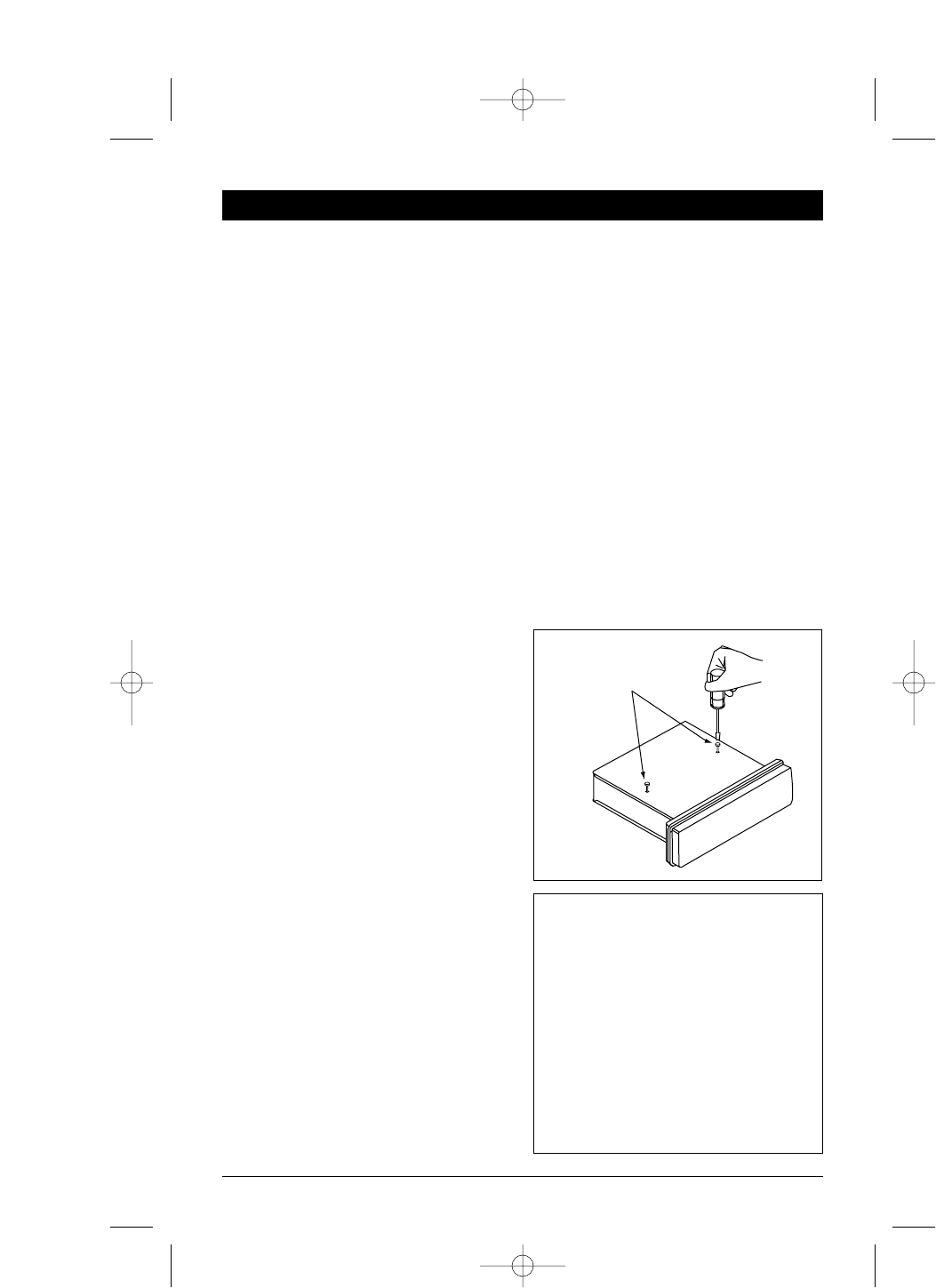
Remove Transportation Screws: Before installing
the unit, please remove the two screws shown in the
illustration below.
Remove Transportation
Screws Before
Installation
M3100CDUM .qxd 07/24/03 4:17 PM Page 8