SP1200 – 21
Using the EQ
Each local
MIC/LINE INPUT
has a 2-band
equalizer for adjusting the lows or highs on the
microphone signal. When the controls are set to
“
U
” (unity), the EQ has no effect on the signal.
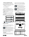
Using the PRE OUT/AMP IN
Connections
The
PRE OUT
and
AMP IN
connectors are
provided to give you more flexibility in your system
design. The SP1200 is shipped with U-shaped
jumpers installed between the
PRE OUT
and
AMP
IN
jacks. This routes the signal from the output of
the preamplifier stage to the input of the amplifier
stage.
This also provides a point in the signal chain to
insert an external signal processor. Simply connect
the line-level signal from the
PRE OUT
jack to the
input of the processor, and connect the line-level
output from the processor to the
AMP IN
jack on
the SP1200.
Another option that is available is to connect
another amplifier into the system. Simply use a
Y-cord at the
PRE OUT
jack to split the signal
between the
AMP IN
jack and the input jack on an
external amplifier.
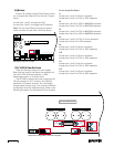
Zone A Output
The amplifier output on the SP1200 can be used
with an 8-ohm impedance load, or to drive a 70V or
100V distributed system directly (also called
constant-voltage systems).
Direct Speaker Connection
If the SP1200 is not being used in a distributed
speaker system, you can reconfigure the amplifier
to drive an 8-ohm load. Each amplifier can provide
up to 200 watts into an 8-ohm load. See the
"Internal Settings" section on page 13 for
instructions on how to reconfigure the amplifiers.
Distributed Speaker System
When using the SP1200 in a 70V or 100V
system, connect the speaker output directly to the
distributed system. The SP1200 can directly drive a
distributed system's speaker line without the need
for an output transformer. The SP1200 can supply
up to 200 watts into a 70V or 100V distributed
system. Make sure the taps on the speakers in the
system do not exceed a total of 200 watts.
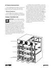
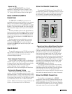
Using the Remote Connection
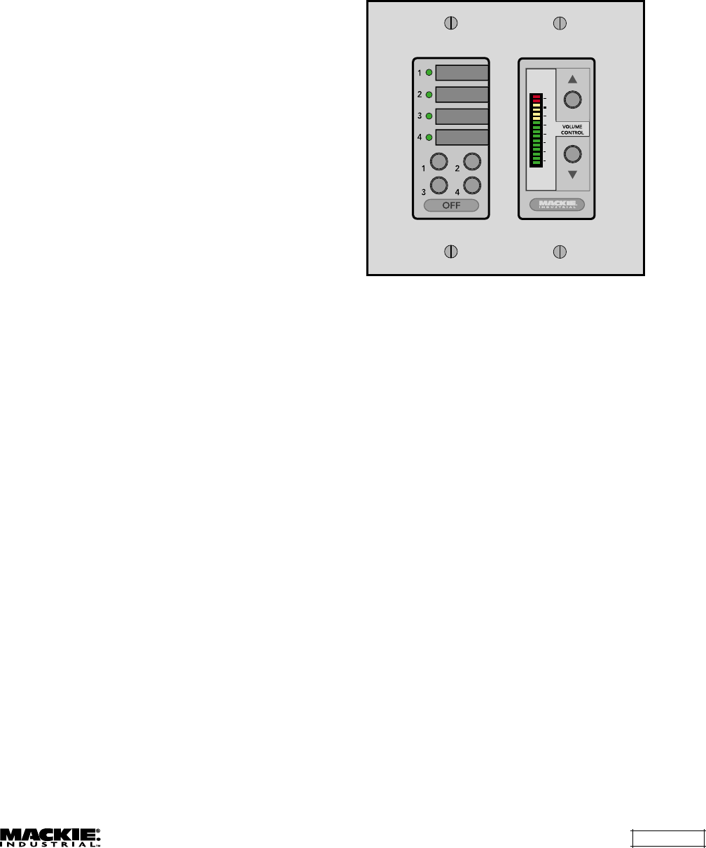
The optional SP1200 Remote Control (SP-41R)
provides Input Selection and Master Volume control
for each amplifier or zone. The Remote Control can
be mounted in a standard double-gang electrical
box and covered with a Decora
®
-style faceplate.
3
0
3
6
9
15
30
55
MASTER
LEVEL
Connecting One or More Remote Controls
Each Remote Control affects only the zone to
which it is connected. Up to ten remote controls
may be connected to each zone simultaneously.
This allows controls to be conveniently placed.
Each control will interact with the SP1200, and all
controls will reflect the current source and level
settings. Note that the remote control indicates the
gain setting and not the actual signal level in real
time. In addition, the SP1200 provides a method for
controlling two independent zones using a single
Remote Control by assigning them to the same
AMP ADDRESS
(see next section).
The maximum distance between the remotes
and the SP1200 varies, depending on the type of
cable selected and the number of remote controls
used. Typically, a lower wire gauge and cable
capacitance allow longer distances. See the instruc-
tions with the remote control for more information.
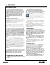
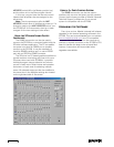
Using the RS485 Connection
The amplifier is equipped with an
RS485
connection. When two SP1200s are linked via the
RS485 connection and assigned to the same zone
(AMP ADDRESS switches 1-5), the Input Selection
and MASTER VOLUME buttons on both amplifiers
track each other. One unit must have
AMP


