10
M-Series
M-Series
M-Series Features
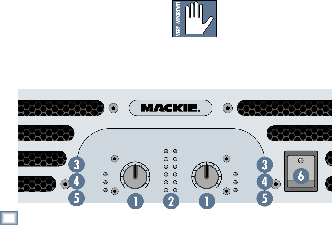
Front Panel
Much of the front panel of the M-Series amplifiers is
comprised of ventilation slots for expelling warm air from
the inside of the amplifier. Be sure to leave space in front
of the amplifier for proper ventilation to occur.
1. Gain Control
These knobs control the levels to the output section of
the M-Series amplifiers. You’ll notice that their travel is
detented, meaning there are 21 built-in “resting points”
so you can easily set both controls to the same level.
Usually, these controls are set all the way up.
The gain structure of the amplifier is designed so that
a +4 dBu (1.23V rms) input signal drives the amplifier
to full power into 4 ohms.
M•2000 = 525 watts/channel into 4 ohms
M•3000 = 800 watts/channel into 4 ohms
M•4000 = 1050 watts/channel into 4 ohms
This is how the sensitivity of an amplifier is defined
(the input voltage required to attain maximum output
power into a specified load impedance). In this case,
it
equates to a voltage gain of 31.4 dB for the M•2000,
33.3 dB
for the M•3000, and 34.4 dB for the M•4000).
With the Gain control all the way up (fully clockwise),
the input sensitivity is 1.23V, which works well with
professional equipment operating at a nominal +4 dBu
level.
On the other hand, you may want your listening level
to be quieter than the M-Series amplifier’s maximum
level. For instance, if you’re using the amplifier as a
control room amp, and your control room is the size of a
telephone booth, you’ll probably never want to hear the
amp at its maximum level.
You can set the Gain controls as low as you like. How-
ever, reducing the Gain controls requires an increased
input level to reach full power at the amplifier’s output.
Like all amplifier controls, you’ll typically determine
the optimal settings during installation or sound check,
then leave them alone, using your signal source (usually
a mixer) to control listening levels as you work. Or play.
2. Meters
The M-Series amplifier’s meters indicate the relative
output level of the amplifier referenced to full power.
The numbers next to the meter’s LEDs are in dB below
full power.
Ideally, the –20, –9, –6, and –3 LEDs will light and
blink at normal signal levels, while the OL LED may
flicker occasionally during peak moments.
OL is short for Overload. Overloading, or clipping,
occurs
when the output voltage no longer linearly fol-
lows the input voltage and simply stops. This causes a
sine wave to “square off,” or get “clipped off.” Thus, the
term clipping. Fear not — this scenario is quite unlike-
ly.
Even with the Gain controls fully up, the M-Series
amplifier easily accepts professional “+4 dBu” operat-
ing levels.
If the OL (Overload) LED is blink-
ing frequently or continuously, turn
down the amplifier’s Gain control or
the source signal (i.e., the mixer’s
master faders).
OL
-3
-6
-9
-2
0
SIG
OL
-3
-6
-9
-2
0
SIG
2
INTERNAL
STATUS
INTERNAL
STATUS
PROTECT
SHO
RT
OVER TEMP
PROTECT
SHO
RT
OVER TEMP
OO
MAXMAX
OO
1
M
.
4000
POWER
H I G H E F F I C I E N C Y P O W E R A M P L I F I E R


