DEFINITY AUDIX System Release 4.0
System Description Pocket Reference
585-300-214
Issue 1
May 1999
Design and Operation
2-9
On-board Cables
For more information about performing maintenance and administration
procedures using the faceplate, see Chapter 3 or
DEFINITY AUDIX
System Release 4.0 — Maintenance,
585-300-121.
On-board Cables
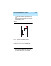
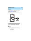
Four on-board cables supply power to the disk drives and allow the
system’s components to communicate with one another:
■ Two H600-500 power cables supply power from the TN568 to the
MO disk drive and the hard disk drive.
■ An H600-501 SCSI cable carries data between the TN568 and
the MO disk drive.
■ An H600-502 SCSI cable carries data between the TN568 and
the hard disk drive.
The H600-501 and H600-502 SCSI cables have protective shielding that
helps prevent electromagnetic interference.
Operating Requirements
Because the DEFINITY AUDIX system operates inside the customer’s
switch, it requires some of the switch’s resources to operate.
Space Requirements
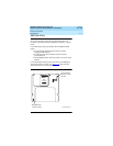
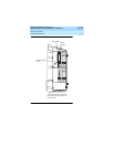
The DEFINITY AUDIX system occupies two universal port slots in a
DEFINITY or System 75 switch or one slot in a CMC.
4
The TN568 circuit
pack connects to the right-hand slot on the backplane, while the MO
disk drive, the hard disk drive, and other components physically block
the left-hand slot.
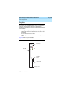
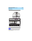
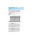
Figure 2-6
shows a sample location for the DEFINITY AUDIX system in a
Single-Carrier Cabinet (SCC). The system can be installed in any two
adjacent port slots in an SCC or Multi-Carrier Cabinet (MCC).
4. For the system to take one slot, it must be installed in slot 6.


