5
Speakers & Volume Controls
6. Multiply 1.14 by 8 (for the S8 setting) = 9.12 Ohms.
7. Next, calculate the overall paralleled impedance Z
O
. Since three paralleled groups are used in this
example, the calculation is as follows:
Z
O
= 1 ÷ [(1÷16) + (1÷16) + (1÷9.12)] = 4.26 Ohms.
Since this yields more than 4 Ohms, the S8 setting for the 4 Ohm group, the S8 setting for the 6
Ohm group and the S8 setting for the 8 Ohm group are the correct ones to use.
Impedance Setting Tips
1. You may use the above method to calculate the correct impedance matching condition for practically
any combination of speakers and RAT1s.
2. Use the lowest "S" setting possible consistent with the requirement to keep above the minimum safe
operating load impedance for the amplifier. You may have to try 2 or 3 values of "S" for each
impedance group and recalculate the overall paralleled impedance Z
O
each time, before you arrive
at the final correct value.
3. When you test the system, you may find volume differences between the impedance groups when all
RAT1s are set to max. volume. This is normal and is usually not a problem, since the user will be
listening at lower levels most of the time. If you feel it necessary to even out the volume levels, move
the "S" jumpers to the next higher number on the RAT1s that feed the loudest group.
NOTE: While speakers of differing impedance can be accommodated using these procedures, it is
highly recommended you not do so on a regular basis. The easiest and best performing installation
is achieved by using speakers of the same impedance throughout the entire system. Then use the
charts to determine the correct jumper "S" settings.
INSTALLATION – COMMON IR BUS SYSTEM
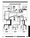
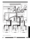
Fig. 3 illustrates a typical installation using three RAT1's along with other Xantech products in a 4-room
multi-room system. The principles shown should be used as a guide when planning your own specific
installations. It is configured as follows:
1. For simplicity, only three RAT1's are shown. Larger systems (up to a max. of 16 using 8-Ohm
speakers) may be used. 16 is the maximum number using 8-Ohm speakers and an amplifier with a
minimum loading impedance of 4 Ohms. See chart, in: Setting the Impedance Matching Jumpers
section).
2. Note that a
Common IR Bus
connects the 780-80 "J" Box IR Receiver, the two MIRV1 Volume
Controls, a 480-00 "Dinky Link" IR Receiver and a Smart Pad
3
keypad to each of the RAT1's. In
addition, it connects to a 789-44 Connecting Block, so that the source equipment can be controlled
from the remote rooms.
3. Since a common IR bus is used, each of the RAT1's and its connected MIRV1 (where used) must use
a different IR Code Group number, so that the volume level in each room can be adjusted independent
of the others.
To make code group changes, refer to the RC68+ Programmer Instructions.
NOTE:
When shipped from the factory, the RAT1 and MIRV1 are set to code group number 30.
If you use group 30 or change to a different number, be sure to always set the RC68+ to the
same number.
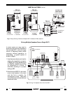
4. When a code group is chosen, "teach" volume commands from the RC68+ Programmer (see Fig. 2)
into learning remote controls (and the keypad), dedicated to each room. You may use the Xantech
URC learning remote controllers for this purpose.
NOTE:
With a Common IR Bus system, you cannot carry the same remote control from room-
to-room. You must use a dedicated remote for each room into which you have "taught" the
specific RC68+ Code Group that operates the specific RAT1 that controls the volume for that
room!
RAT1


