


10
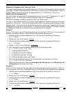
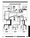
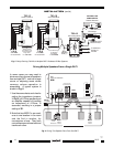
In some cases you may need to
drive more than one set of speakers
from a single RAT1, such as in large
rooms or adjoining areas where
common volume operation is
acceptable. A typical system is
shown in Fig. 6.
1. Use the same charts and rules for
setting the impedance jumpers.
In Fig. 6, all 8-Ohm speakers and
an amplifier capable of handling
an impedance of 4-Ohms, is
assumed; resulting in a jumper
setting of S1.
2. Note that two MIRV1's are used;
one at one location in the room
and the 2nd in another, for
convenience of use. They both
control the same volume level and
track each other.
Driving Multiple Speakers From a Single RAT1
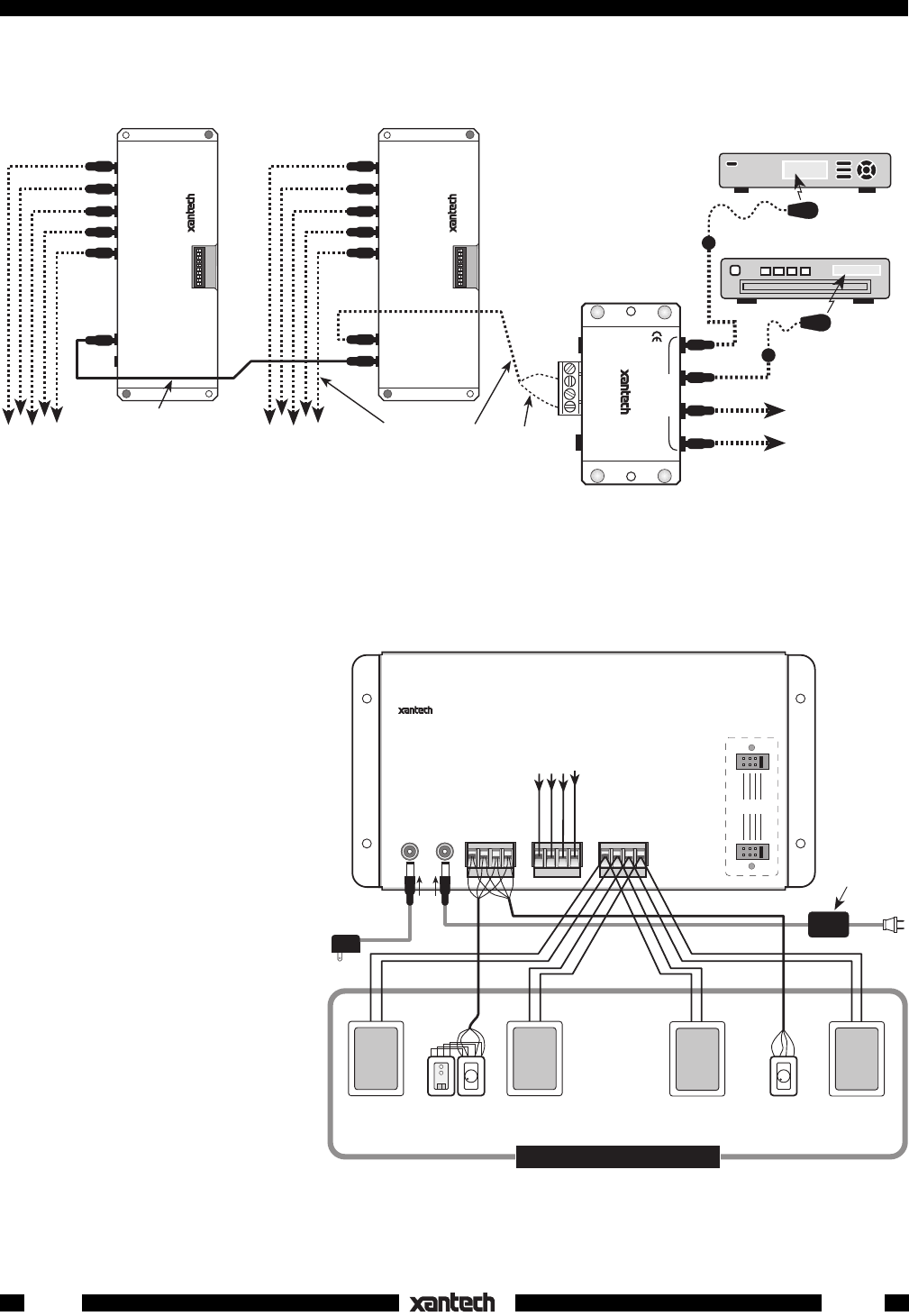
S8
S4
S2
S1
L+
L–
R– R+L+ L–R– R+
AMPLIFIER
INPUT
SPEAKER
OUTPUT
STATUS
POWER
IR IN
STATUS
GND
+12 VDC
12VDC
RAT1
REMOTE AUTO TRANSFORMER
R
L
+– +–
R
L
+– +–
780-80
"J" Box
IR Receiver
MIRV1
Volume
Control
MIRV1
Volume
Control
LARGE ROOM OR AREA
ST G
V
ST G
V
FROM AMPLIFIER
SPEAKER TERMINALS
786-00
Status Power
Supply
782-00
Power Supply
To 120 V AC
(unswitched)
IR
IR
Fig. 6 Driving Two Speaker Pairs From One RAT1
INSTALLATION (cont'd)
12VDC
+12
VDC
GND
STATUS
IR IN
EMITTERS
IR
RCVR
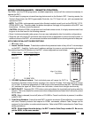
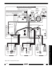
789-44
CONNECTING BLOCK
®
CD Changer
Satellite Receiver
CONTROL
OUTPUTS
LOGIC POLARITY
SELECTOR
A B
CONTROL INPUTS
1 2 3 4 5
1 2 3 4 5 6 7 8 910
ON
283M
Blink-IR™
789-44
Connecting Block
793-10
Serial Combiner
CONTROL
OUTPUTS
LOGIC POLARITY
SELECTOR
A B
CONTROL INPUTS
1 2 3 4 5
1 2 3 4 5 6 7 8 910
ON
793-10
Serial Combiner
White
Stripped
Side (+)
To IR IN
and GND
on each RAT1
To IR IN
and GND
on each RAT1
Use Mini-Plug-
to-Stripped
end cables,
Pt. # 6015900
"Daisy-Chain"
connection. Use
3.5/3.5mm Mini-
Plug cable,
Pt. # 6017400
To additional
Emitters if
needed
+
–
CONTROLLED
COMPONENTS
283M Blink-IR™
Mouse Emitter
793-10
SERIAL CONTROL
COMBINER
793-10
SERIAL CONTROL
COMBINER
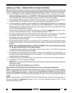
Fig. 5 Daisy-Chaining 793-00's in Multiple RAT1 Dedicated IR Bus Systems
RAT1
12-8-00
Rev.C