


Transmission
7
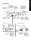
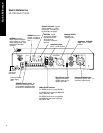
Installation - Audio Connections
(See Quick Reference on pages 3-4.)
OUTPUT Audio
The OUTPUT audio section is composed of an OUT-
PUT audio selection switch, a male XLR balanced
audio OUTPUT connector and two phono unbalanced
audio OUTPUT connectors.
OUTPUT Audio Selection Switch
This switch selects what audio is routed to the OUT-
PUT audio connectors. The switch has three posi-
tions:
1. RX ONLY. In this position, only RECEIVE audio is
routed to the OUTPUT. When the transmitter is
turned off, the unit is squelched and the RECEIVE
audio is muted.
2. RX + AUX. In this position, both the RECEIVE
and AUXILIARY audio are mixed and routed to
the OUTPUT.
3. RX or AUX. In this position, the OUTPUT audio
is either RECEIVE or AUXILIARY audio. When
the RECEIVE audio is squelched (indicated by the
illumination of the SQUELCH LED on the front
panel), AUXILIARY audio is routed to the OUT-
PUT. When RECEIVE audio is not squelched,
RECEIVE audio is routed to the OUTPUT.
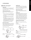
Balanced Audio Output
When connecting to the XLR balanced OUTPUT, use
the pin out shown below. If the output is unbalanced,
either use the unbalanced phono connectors or wire
the balanced XLR output as shown below with pins 3
and 1 wired together. The OUTPUT audio has a
nominal output level of 0dBu.
XLR pin out diagram for a balanced connection:
Pin 2 +
Pin 3 –
Pin 1 Shield
XLR pin out diagram for a unbalanced connection:
Pin 2 +
Pin 1 and 3 –
LINE/MIC Switch
This switch reduces the OUTPUT level of the bal-
anced OUTPUT audio only. It does not affect the
OUTPUT level of the unbalanced audio. The OUT-
PUT audio is reduced by 40dB to microphone level
when this switch is selected to MIC.
Unbalanced Audio Output
There are two unbalanced phono audio OUTPUT
connectors. The nominal OUTPUT audio level is
–10dBu.
AUXILIARY Input
The LR-100 has an AUXILIARY input that allows for
greater functionality of the unit for a variety of appli-
cations. The AUXILIARY input consists of a bal-
anced input, combination connector (female XLR and
¼ in) and two unbalanced phono connectors. All of
these inputs are actively mixed together. Thus, any
combination of input sources can be used. Input level
is adjusted via the front panel trim pot labeled AUX
LEVEL ADJUST. Adjust this level to fit the needs of
your installation ensuring the last red LED on the VU
meter is not illuminated (indicating peak audio).
AUXILIARY Balanced Audio Input:
The nominal input level for the balanced input is
0dBu.
Female XLR / ¼ in combination connector pin outs:
Pin 2 (tip) +
Pin 3 (ring) –
Pin 1 (sleeve) Shield
AUXILIARY Unbalanced Audio
Input:
The nominal input level for the two unbalanced inputs
is -10dBu.
Female XLR / ¼ in combination connector pin outs:
Pin 2 (tip) +
Pin 1 and 3 ring/sleeve
LR-100 Installation