


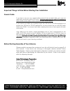
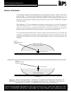
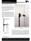
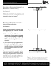
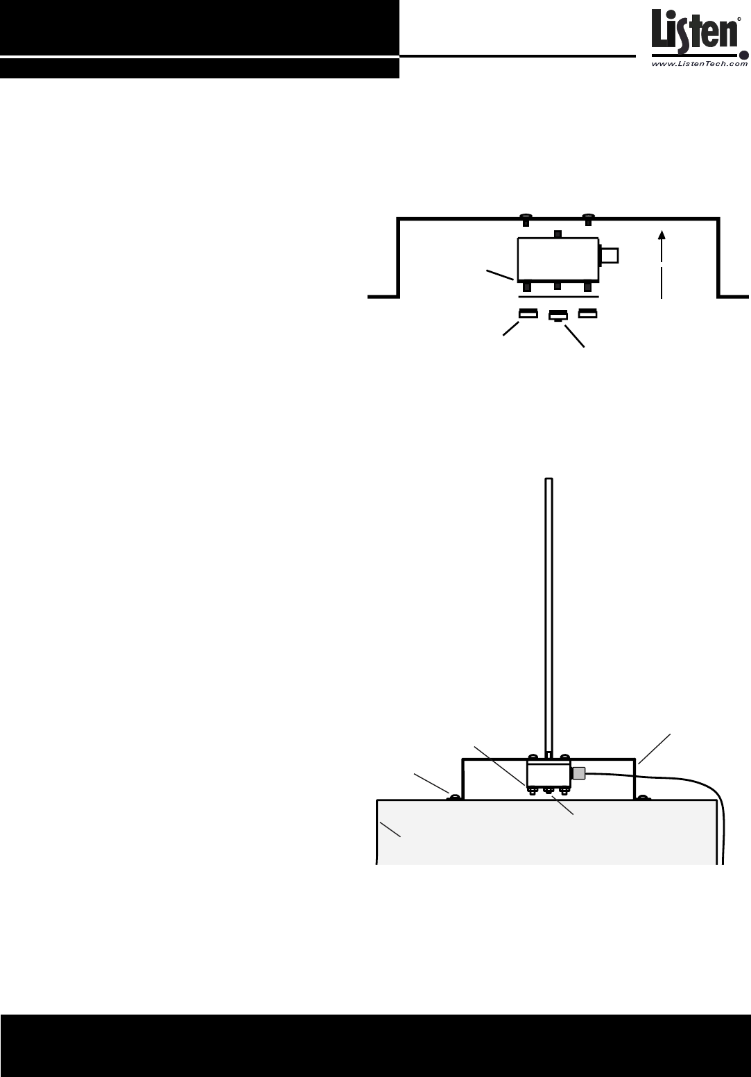
Diagram J. A reversed Antenna Module with Ground Plane
and Shorting Plate.
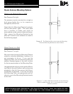
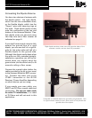
Mount to a Metal Surface Using the Ground Plane and Shorting Plate
See Diagram J
It is often convenient to place an antenna
on top of a metal equipment rack. In order
for the antenna to function properly, it must
be secured to the equipment rack using the
Grounding Plate and Grounding Base.
The Mounting Bracket is not used in this
configuration. Remove the four nuts and
screws from the Antenna Module and care-
fully remove it from the bracket. With a
lockwasher still over each screw, put the
screws through the Ground Plane. Make
sure the ground side of the Antenna Mod-
ule (as indicated on the module) is oriented
AWAY from the Grounding Plane. Then,
slide the Shorting Plate over the ground side
(bottom) of the module. Replace the four
nuts on the bottom of the assembly. Then,
place a Hex Kep nut on the center ground
post and tighten.
Secure the Ground Plane to your metal rack
using sheet metal screws.
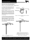
Attach the proper Monopole antenna ele-
ment to the Antenna Module. Systems on
72 MHz will use the LONGER antenna; sys-
tems on 216 MHz will use the SHORTER one.
Connect the supplied coaxial cable between
the Antenna Module and the stationary
transmitter or receiver. If you use your own
coaxial cable, be sure to use cable and con-
nectors rated at 50 Ohms.
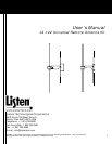
LA-122 Universal Antenna Kit
LISTEN TECHNOLOGIES CORPORATION 8535 South 700 West, Suite A Sandy, Utah 84070-2515 USA
Phone: +1.801.233.8992 USA Toll Free: 1.800.330.0891 Fax:+1.801.233.8995 e-mail: info@listentech.com
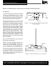
Ground Plane
Shorting Plate
Ground side of
Antenna Module
Hex Kep nut
Screws from Antenna Module
Nuts from ground side
of Antenna Module
Metal Equipment Rack
Ground Plane
Sheet metal
screws
Shorting Plate
Hex Kep Nut
Diagram K. Mounting a Monopole on a metal surface.
12