


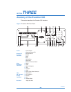


21
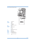
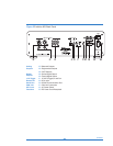
Remote Connections on the Back Panel
31 12 VDC (Trigger) In and Out
The output sends 12 VDC power on/off signals to other Krell components and
other devices that incorporate a 12 V trigger.
The input receives 12 VDC power on/off signals from other components and
devices that incorporate a 12 V trigger.
33 RC-5 Input
The RC-5 remote connector is used with a third party remote control system
that provides RC-5 (IR) data with the carrier intact, via a wired connection. A
stereo tip, ring, sleeve 1/8-inch mini connector is used in the following config-
uration: Tip = RC-5 data, Ring = +5 V, Sleeve = GND.
27 CAN Link
These RJ-45 link connectors are connected in parallel. They are used to con-
nect the Evolution 505 in link mode, to other CAN Link-enabled Krell prod-
ucts.
32 RS-232 Communication Port
This port allows you to send operational instructions to the Evolution 505
using an external computer control system. The RS-232 port uses a 9-pin
D-subminiature connector.
Power
34 AC Power Switch
Use this switch to change the Evolution 505 from off to stand-by.
35 IEC Power Cord Receptacle
Use the provided IEC standard 15 amp power cord.