


KRAMER ELECTRONICS LTD.
13
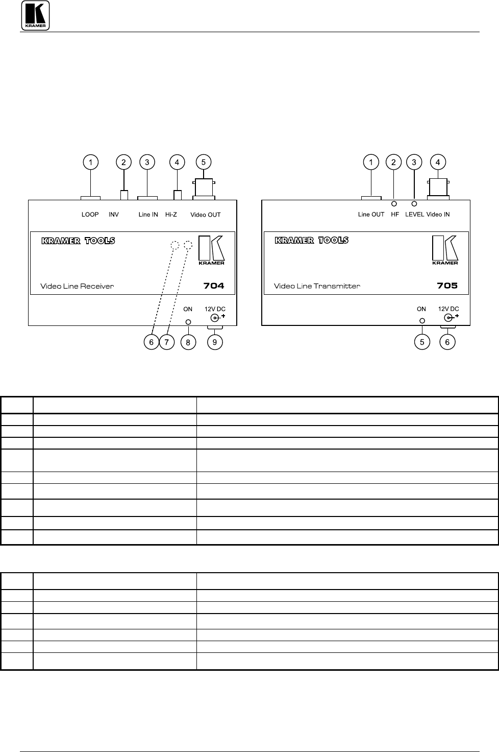
7.2 Getting to Know the 705/704 Video Line Transmitter/Receiver
The KRAMER 705 Video Line Transmitter and the 704 Video Line Receiver, part of the KRAMER TOOLS
family, are used as a pair for transmitting video over long distances using a twisted-pair wire. A termination
switch allows several 704 receivers to be looped-through on the same line (one transmitter-multiple receivers.)
The frequency response of the pair is well over 6.7MHz, even at 400m. At shorter distances, they provide close
to broadcast level performance. The machines offer user controlled Gain and HF compensation.
NOTE
For Installation, operation, maintenance and troubleshooting instructions please refer to sections 8-13.
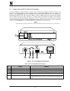
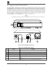
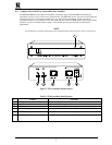
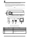
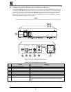
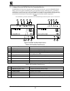
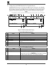
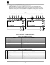
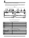
Figure
: 705/704 Front/Rear Panel Features
Table 8: 704 Front/Rear Panel Features
No.
Feature Function
1.
LOOP
telephone socket Provides video looping capability to increase number of outputs.
2.
INV
switch
Inverts the incoming balanced signal.
3.
Line IN
telephone socket Balanced input.
4.
Hi-Z
switch Selects "
Term
" or "
Hi-Z"
impedance (pressed=
Term
;
for end of line).
For looping select "
Hi-Z"
.
5.
Video OUT
BNC connector
Amplified and buffered video output.
6.
LEVEL trimmer
Adjusts the video level output (accessible from bottom).
7.
HF trimmer
Controls cable equalization of the video output (accessible from bottom).
8.
ON LED Illuminates when the machine is powered.
9.
12VDC
feed connector A DC connector that allows power to be supplied to the unit.
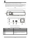
Table 9: 705 Front/Rear Panel Features
No.
Feature Function
1.
Line OUT
telephone socket Amplified and buffered balanced output.
2.
HF trimmer
Controls cable equalization of the output.
3.
LEVEL trimmer
Controls level of output.
4.
Video IN
BNC connector Video input.
5.
ON
LED
Illuminates when the machine is powered.
6.
12VDC
feed connector A DC connector that allows power to be supplied to the unit.