


10
7
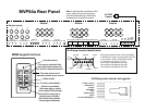
8. Connect the emitters to the IR Emitter ports on the rear of the
MVP64a. Single or dual emitters can be used. If a Xantech 590-00 is
being installed do not connect emitters in the MVP64a IR Emitter #1.
9. When connecting two or more MVP64a's in the same home,
connect the amps together using stereo 3.5mm plugs (all three wires
are used) to the data plug on the rear of the MVP64a. The MVP64a's
share power on and off data as well as infrared signals.
The MVP64a source input RCA jacks are Y-corded
together on all amps (source 1 left/right on amp 1
to source 1 left/right on amp 2 etc.)
10. Connect the AC power into an outlet that can supply at least six
amps (700 watts) dedicated to each MVP64a.
11. If a Xantech 590-00 is to be installed, the 590-00 needs to be
wired to the MVP64a removable 8 terminal connector and the
590-00 has to be programmed.
Wiring the 590-00 to the MVP64a
The wire/plug from the 590-00 IR emitter port 1 is a mono 3.5mm
with the stripewire to the center/end of the 3.5mm connector. The
rest of the wires can be almost any type.
MVP64a to Xantech 590-00
The Xantech 590-00 is an infrared learning "remote" capable of
converting a dry contact closure of each of the MVP64a's four
functions, power-on (TON) and power-off (TOFF) to an IR
macro sequence of up to 10 commands each.
The 590-00 power supply is shipped with the 590-00. Power to
the 590-00 should be on all the time (like a TV set) so the system
IR commands can be sent as soon as any MR60 source buttons are
pressed.
The first time installing and programming a 590-00 connected to a
MVP64a can be a bit tricky, so please follow these directions closely.
See the diagram on page 7.
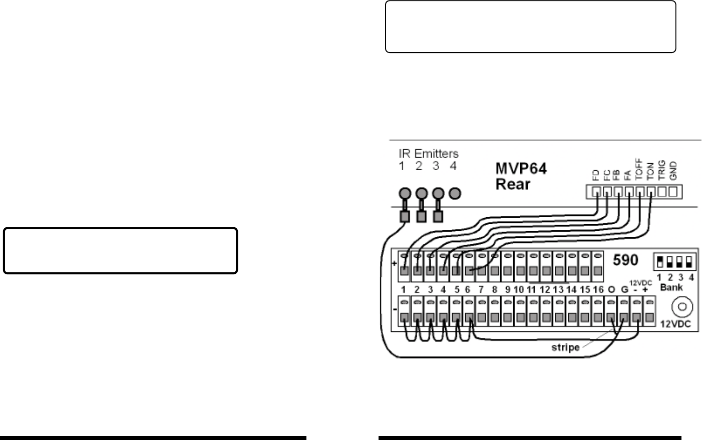
Connect the 590-00 rear panel "O" and "G" terminals to the wire pair
on the 3.5mm to wire pair (installer supplied). Connect the black wire
with the stripe to the "O". Next insert the 3.5mm plug into the rear of
the MVP64a labelled "IR Emitters" and "1".
With any type of single conductor wire connect the 590-00 bottom
row - terminals 1, 2, 3, 4, 5, 6 and the -12VDC terminal.
DO NOT connect any wires to the TRIG
terminal on the MVP64a at this time.
Now connect the MVP64a terminal FD to the 590-00 top row +
terminal 1. Next connect the MVP64a terminal FC to the 590-00 top
row + terminal 2.
Continue by individually connecting the MVP64a FB, FA, TOFF and
TON to the 590-00 top row + terminal 3, 4, 5 and 6. If all of the
source equipment has the same IR commands for power-on and
power-off, move the wire on the 590-00 connected to terminal +5
(on the + row) with the wire on the 590-00 terminal +6.