


...System layout considerations continued
In certain commercial applications a microphone paging override
is required. Model MR171 paging and override module takes a
balanced or unbalanced mic, (with defeatable phantom power) or
a line level input and when activated overrides all inputs (even if
some or all zones are in standby) and pages at a preset volume in
all zones.
A variety of door chime and telephone paging, door entry and
front door camera modules are being developed. Check our web
site for more information.
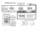
The MVP64a includes a 12VDC trigger output to control and power
various items when the MVP64a is powered up. When the MVP64a
agoes into standby the trigger output ends. It's maximum output is
60mA.
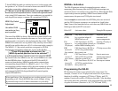
An innovative IR connection system is also included to turn on and
off the various source components as well as four separate
commands. A Xantech 590-00 controller is required for this
purpose. The Xantech 590-00 is a an IR sequence generator. When
it receives commands from the MVP64a it generates an IR command
or sequence of up to 10 commands.
The on command is automatically generated when the MVP64a goes
out of standby and into power up. The off command is automatically
generated when the MVP64a goes from power on to standby. These
sequences are generally used to turn on and off the source equipment.
To activate the four commands, when the system is powered up,
press the MR60 keypad button FNC then quickly press one of the
four source buttons on the top of the MR60 keypad. This will
initiate a pulse at the MVP64a FUNCTION output, that in turn
generates an IR command that is pumped back into the MVP64a IR
emitter port 1 and out to the various emitters connected to ports
2-3-4, that will initiate the command to the source component.
4
13
in bank 1 positions 1 through 6).
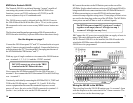
The 590-00 can learn up to 16 different commands on each of its
four banks. If more than 10 different IR commands are to be stored
use bank 2, 3, and 4 to store the sequence commands and bank one
positions 1-6 to execute the sequences.
1. Write down the order for each of the sequences required for all
of the six functions (not programmed with single commands).
2. Turn the bank 2 dip switch on; bank 1, 3, and 4 off.
3. Push PGM (program lamp goes on).
4. Using the wire attached to the 590-00 +12VDC, touch and
hold the other end of the wire to the 590-00 upper + row
terminal 1. While holding the wire in place, press the remote
control button of the first function while the remote is about
2-4" from the 590-00 internal infrared sensor. The 590-00
PROGRAM lamp will flicker while storing the IR signal.
When the IR signal is stored, the confirm lamp comes on.
Release the remote control button and release the wire to the
upper row terminal. The IR signal is now stored in the 590-00
bank 2 terminal 1.
5. Hold the end of the wire to the 590-00 upper + row terminal
2. While holding the wire in place, press the remote control
button of the second function while it is about 2-4 inches from
the 590-00 internal infrared sensor. The 590-00 PROGRAM
lamp will flicker while storing the information. When the
information is stored, the confirm lamp will come on. Release
the remote control button and release the wire to the upper
row terminal. The IR signal is now stored in the 590-00 bank 2
terminal 2.
6. Continue this procedure until all of the required sequence
commands have been learned by the 590-00. If more than 16
IR signals have to be learned, fill up bank 2 with the first 16
IR signals, then turn the bank 2 dip switch off, and the bank 3
switch on. Continue with bank 3 position 1, 2 etc. Use bank 4
positions 1, 2, etc., if required and bank 1 positions 7-16.
Note: When storing an IR signal command sequence, it is most
reliable if commands to a component are timed as far apart as