


2
Congratulations and thank you for choosing the Knöll MVP64a power
amplifier. The MVP64a is designed to meet the amplifier needs of
custom installed multi-zone systems where high quality sound is a
specific requirement as well as ease of installation and operation.
Key Features:
1. Individual zone, four source selection. Each of the six rooms can
select any of the four stereo sources.
2. Individual mute, volume, bass, treble and balance adjustment.
Each of the six stereo channels feature adjustments for bass, treble and
balance. Individual room keypads control volume and mute. Any keypad
can turn the whole system on or off.
3. Cost and size efficiency. The MVP64a consists of a total of 6
stereo power amplifiers with individual volume control electronics in a 3-
1/2" enclosure. Each power amplifier channel can deliver 50 watts RMS.
4. Automatic protection circuitry. Each MVP64a channel is
individually and fully protected against low impedance, overheating,
overloading, overvoltage and undervoltage. The protection circuitry
automatically restores the amplifier channel as soon as its parameter
returns to the safe operating area.
5. External trigger and functions out. An 12VDC trigger output is
provided to turn other components on or off. Six function ports are
provided (connects to a 590-00) to turn on and off components via IR as
well as provide four IR commands, source from the MR60 keypads
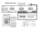
6. Stackable 17" chassis. The MVP64a can be stacked or placed in a
19" EIA equipment rack (requires RK-AMP kit).
7. Data port. For larger systems, multiple MVP64a's can operate in
tandem so all MVP64's turn off and on together and share infrared signals,
page, connect to door chimes, connect to external controllers, etc.
8. Cooling fan. Fans maximize system performance and helps to avoid
early protection system distortion.
9. All on and all off. MR60 keypads turn on any source in all rooms.
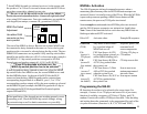
10. Volume level indication. MR60 keypads display volume level on
top three rows of buttons. FNC-MUTE level is the lowest.
11. All room volume up and down (rooms on only) via FNC button.
15
Troubleshooting
If a problem is encountered with the MVP64a, the most expedient
procedure is to locate the problem and if possible repair it before
requesting service. Be sure to carefully check other system
components such as controllers, CD players, volume controls, wiring,
speakers, etc. that may be at fault.
Problem Action
Power indicator does 1. Check that the MVP64a is plugged in.
not light - no sound 2. Test the AC outlet with a lamp..
3. Check that the MVP64a power button is
on (in).
Sound cuts out 1. Verify speaker impedance is 4-16 ohms.
Changing speakers may be required.
2. Check if the MVP64a feels hot. If it's
hot, increase cooling - see Installation.
Sound is distorted 1. Turn the volume down
2. Check speakers for damage.
3. Check inputs for proper levels.
Source output levels may need adjustment.
4. Speakers may have less than 4 ohm rating
5. If inputs are Y corded to another MVP64a
or stereo receiver, make sure all amps are
turned on or a MR24 buffer may be required.
MVP64 does not 1. Press any MR60 keypad "OFF" button or
turn off RB8 remote "POWER" button for 5 seconds.
The MVP64a should power down and the
MVP64a led turns orange (standby). Before
turning the MVP64a power switch off (out)
we suggest that the MVP64a be in standby
Speaker pops when 1. Speaker may need resistor placed across
amp turned on or off terminal. We suggest 2k0 1/4 w resistor
which discharges the speakers internal
capacitor.