


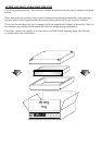
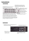
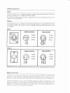

Front Panel Functions
The power switch is a two pole type,
isolating both the live and neutral
conductors. When the power is on,
a red status LED lights.
The input level control allows
the system gain to be up to+6dB
when in its fully clockwise position,
and offers full attenuation in
its anti-clockwise position.
The scale switch
bypass
selects maximum boost and cut
for the equaliser of either 6dB or12dB. The centre
position of this switch performs the function,
which silently removes the graphic equaliser section
from the signal path.
Low cut filter switch enables a 30Hz subsonic
filter to be connected in or out of circuit.
The Overload LED The signal level is monitored at several
separate points within the circuitry of the unit, and any one of these
signals exceeding a threshold, set 3dB below clipping, will cause the
LED to light. This threshold is set at +19dB, but it must be remembered
that excessive boost of some frequencies combined with a high average
input signal, can occasionally cause this level to be exceeded. In this
event, the input level control should be turned down to correct the problems.
However, if the input signal itself exceeds +19dBu the input stage will be
overloaded. If this problem arises, the signal level from the output of the
preceding piece of equipment must be turned down.
The high quality faders used in this equaliser have an
oil-damped action for smooth operation and feature a
centre detent following accurate "flat" setting.
The serial number of this unit should be
quoted in any correspondence concerning
the unit.
Rear Panel Functions
Main is supplied via an IEC
standard 3 pin connector. A
compatible power cable
is supplied with the unit.
Input and output connections are made
via complementary XLR style sockets.
The mains fuse is located in a fuse holder, fitted to the rear panel.
Always replace with the correct type and rating of fuse, as
indicated adjacent to the fuse holder.
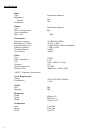
Instrument Familiarisation
4