


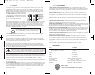
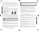
The WX amplifier outputs dangerous voltage levels
from the voice coil (speaker) outputs and can cause
serious injury or death from electrocution. Never
contact the voice coil outputs, connect s
peakers, or
contact speaker wires while the amplifier is turned on.
Voice Coil 1
Voice Coil 2
Voice Coil 1
Voice Coil 2
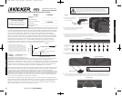
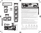
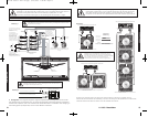
Operation
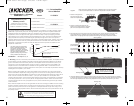
Within the control panel shield, the Kicker WX amplifier has five (5) rotary controls, input jacks for the
Remote Bass level control, and input/output jacks for the optional WX control module. The control
panel delivers a full range of options for processing the signal that powers your subwoofers. To remove
the control panel shield, simply remove the two (2) screws as shown in Figure 2.
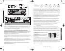
1. InputGainControl The input gain control is not a volume control. It matches the output of the
source unit to the input level of the amplifier. Please use hearing protection before performing the
following procedure. Disconnect the Remote Bass level control and turn the source unit up to about
3/4 volume (if the source unit goes to 30, turn it to 25). Next, slowly turn (clockwise) the gain on the
amplifier up until you can hear audible distortion, then turn it down a little.
2. BassBoostControl The bass boost control is designed to give you increased output 0 - 18dB
at 40 Hz. The setting for this control is subjective. If you turn it up, you must go back and adjust the
input gain control to avoid clipping the amplifier.
3. HighPassSubsonicCrossover The variable high-pass crossover located on the control panel
utilizes a 24dB per octave 20 - 60Hz high-pass crossover. The setting for this control is subjective but
should be adjusted to appropriately accommodate your enclosure in order to prevent damage from high
excursion and increase the power handling of the subwoofer(s).
4. LowPassCrossover The variable low-pass crossover located on the control panel utilizes a
24dB per octave 50 - 200Hz low-pass filter. The setting for this control is subjective; 80 Hz is a good
place to start.
5. AdjustableLimiterControl The limiter adjusts the maximum RMS output of the Warhorse. If your
vehicle’s charging system is inadequate to provide full power to the WX series amplifier, adjust the limiter
control clockwise to reduce the amplifier’s power consumption and maintain an operational level that will
protect your subwoofer(s) from damage. If the <VOLT LED is on and the amplifier is frequently shutting
down due to under voltage, try turning the limiter control up (clockwise) until this is no longer a problem.
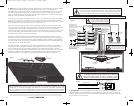
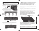
6. RemoteBass(Level Control) With the remote bass level control, you have the ability to control the
level of the subwoofer(s) remotely. To mount the remote bass level control, simply screw the metal
bracket to the chosen location. Then slide the housing onto the bracket until it snaps into place. Run
the cable from the controller to the “Remote Bass” jack on the amplifier chassis. See Figure 7.
7. WarhorseControlModule The optional Warhorse control module opens up a wide range of
operational possibilities within the Warhorse. The control module can simultaneously control up to 16
WX amplifiers and puts additional signal processing features in the palm of your hand. These include
bandpass crossover with adjustable slopes, limiter adjustment, phase inversion, single-band parametric
equalization, voltage range adjustment, battery voltage display, tone generator, and individual amplifier
muting. Contact your Kicker dealer for more information about the Warhorse control module and its
features. It is necessary to purchase the control module to access the full range of possibilities available
from your Kicker Warhorse amplifier.
OPERATION
Voice Coil 1
Voice Coil 2
Figure 7
Mount the metal bracket
Back View
Side View
4 Conductor
Phone Cable
Slide the
housing until
it snaps into
the metal
bracket
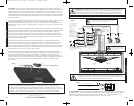
Voice Coil 1
Voice Coil 2
Coil 1
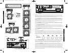
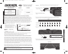
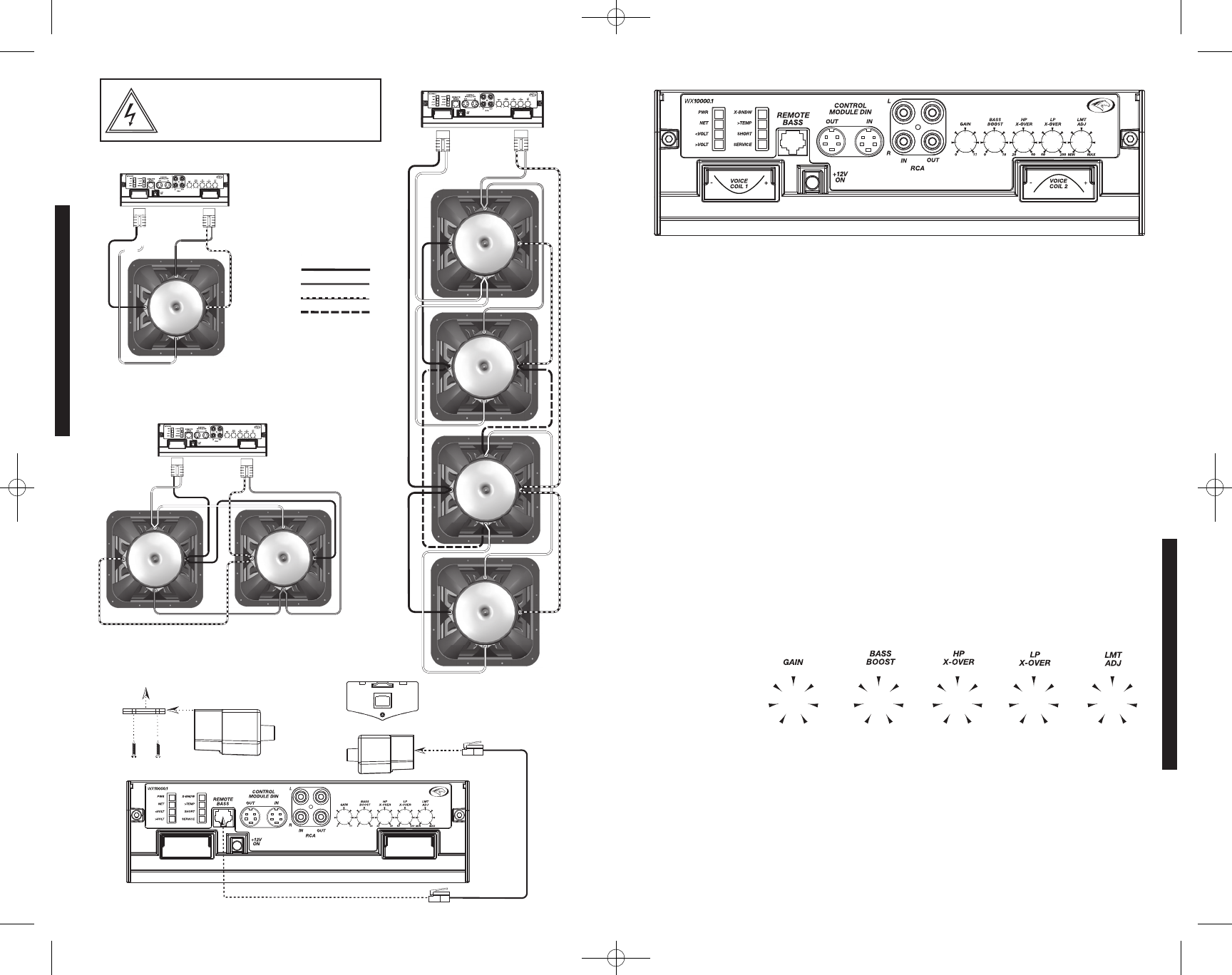
Use 8 Gauge Speaker Wire
2 Ohm Dual-Voice Coil Subwoofer
Two (2) 4 ohm Dual-Voice Coil Subwoofers
-+
Coil 2
Figure 6
Minimum
2 Ohm
Load
Minimum
2 Ohm
Load
Minimum
2 Ohm
Load
Minimum
2 Ohm
Load
-+
-
+
Minimum
2 Ohm
Load
Minimum
2 Ohm
Load
-
+
Coil 1
Coil 2
Coil 1
Coil 2
Coil 1
Coil 2
Coil 1
Coil 2
Four (4) 2 ohm Dual-Voice Coil Subwoofers
WX10000.1AMPLIFIER
6 7
-
+-
+
CONFIGURATION
Hz
50
70
95
125
155
185
200
V
5
3.5
1.6
0.8
0.4
0.25
0.17
dB
0
2.5
5.5
9
12.5
15
18
Hz
20
25
30
40
45
55
60
%RMS
100
80
50
30
20
15
10
Figure 9
The corresponding value for
each marker is given for each of
the Warhorse amplifier’s rotary
controls to assist in the precise
adjustment of your system.
Figure 8
-
+
-
+
-
+
-
+
-
+
-
+
-
+
-
+
-
+
-
+
Use 8 Gauge Speaker Wire
Use 8 Gauge Speaker Wire
Coil 1
Coil 2
-
+
-
+
Coil 1
Coil 2
-
+
-
+
Voice Coil 1 +
Voice Coil 1 -
Voice Coil 2 +
Voice Coil 2 -
Series Wire
Wiring Key
Use 8 Gauge Speaker Wire
2007 WX 10000-1 4in1 v01.qxp 4/25/2008 1:46 PM Page 4