


54
|
English
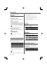
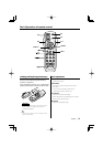
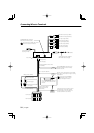
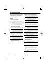
Connecting Wires to Terminals
£
Ó
Î
{
x
È
Ç
n
£
Ó
Î
{
x
È
Ç
n
1/
*°" /
/°" /
8/°" /
," /
,,
-1
7"",
18Ê
Battery wire (Yellow)
Ignition wire (Red)
FM/AM antenna
input
Antenna Cord (ISO)
Antenna Conversion Adaptor
(ISO–JASO) (Accessory3)
Wiring harness
(Accessory1)
If no connections are made, do
not let the wire come out from
the tab.
Power control/ Motor
antenna control wire
(Blue/White)
TEL mute wire (Brown)
Connect either to the power control
terminal when using the optional
power amplifier, or to the antenna
control terminal in the vehicle.
Connect to the terminal that is grounded
when either the telephone rings or during
conversation.
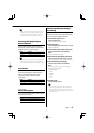
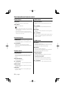
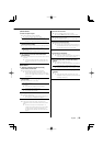
A-–7 Pin (Red)
A–4 Pin (Yellow)
Connector A
Connector B
Fuse (10A)
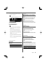
To External Display/
Steering remote
See next page
To connect the KENWOOD
navigation system, consult
your navigation manual.
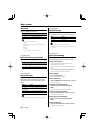
External amplifier control wire
(Pink/Black)
To "EXT.AMP.CONT." terminal of the
amplifier having the external amp
control function.
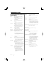
Front left output (White)
Front right output (Red)
Rear right output (Red)
Subwoofer left output (White)
AUX left input (White)
AUX right input (Red)
Subwoofer right output (Red)
Rear left output (White)
To connect these leads, refer to the
relevant instruction manuals.
To KENWOOD disc changer/
External optional accessory