


XD-951/A900/A700 (En)
11
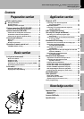
Preparation section Basic section Application section Knowledge sections
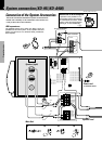
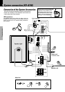
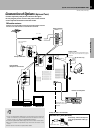
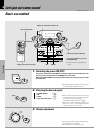
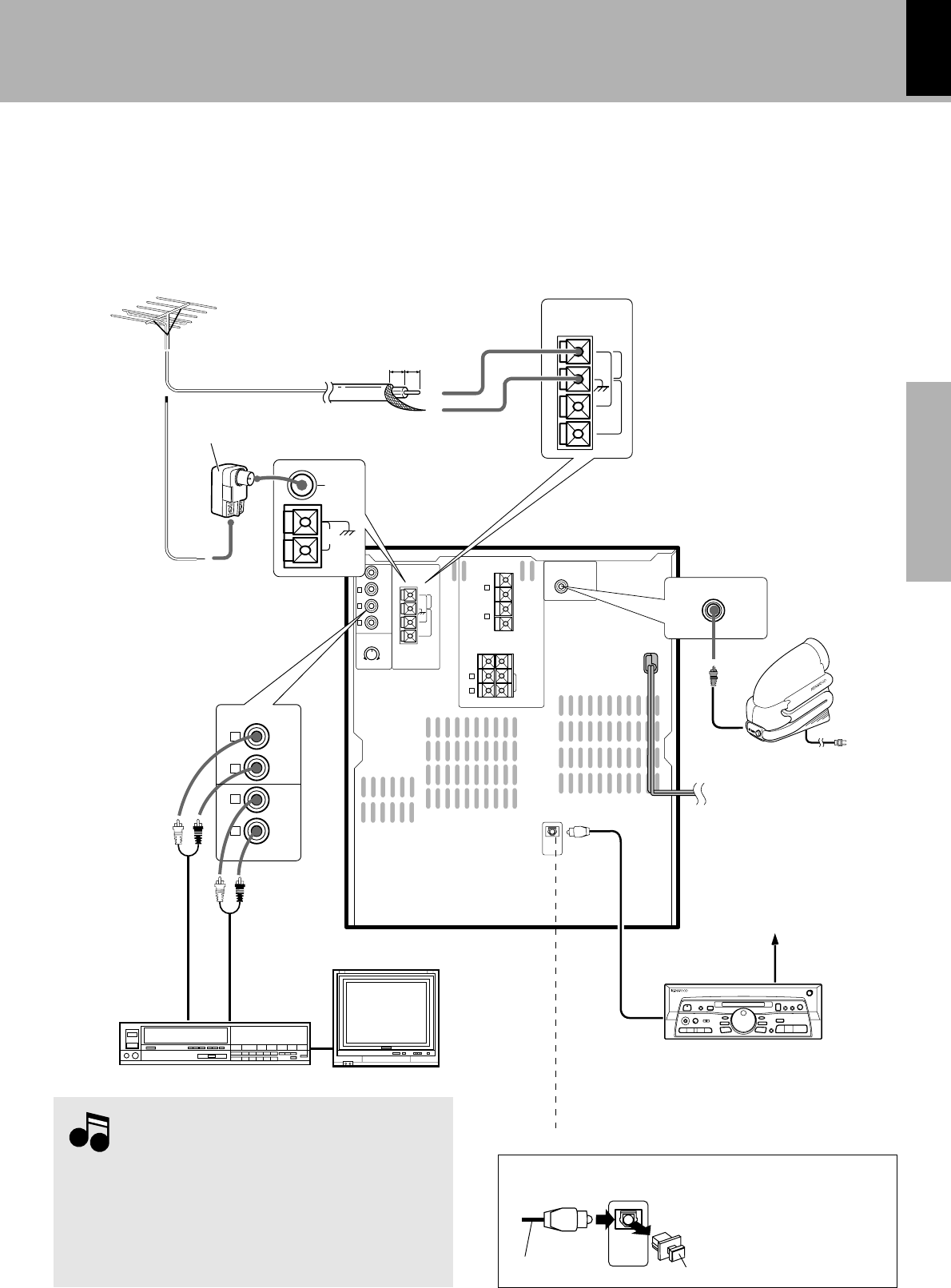
Connect separately sold parts as shown in the figure.
Do not plug the power cord into the power outlet until all
of the required connections have been made.
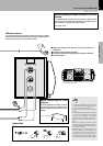
Connection of Options
(Optional Parts)
System connection (XD-951/XD-A900/XD-A700)
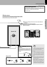
DIGITAL OUT jack (OPTICAL)
DIGITAL
OUT
OPTICAL
If necessary, remove the cap and
plug the optical-fiber cable (op-
tional).
Audio output
Cap
Optical-fiber cable
Optical-fiber cable
(Provided with the MD
recorder)
Audio input
MD recorder
Super woofer
Extremely low sound is played back pow-
erfully. This can be used with any type of
playback.
1. All of the optical-fiber cables sold in audio stores cannot always be
used. If the cable you purchased cannot be connected to this unit,
please consult your dealer or KENWOOD distributor.
2. Insert the optical-fiber cable straight into the connector until it clicks.
3. Be sure to attach the protection cap when the connector is not
used.
4. Never band or bundle the optical-fiber cable.
Notes
Notes
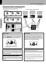
FM outdoor antenna
Lead the 75Ω coaxial cable connected to the FM outdoor antenna
into the room and connect it to the FM 75Ω termimal.
Antenna adapter
(optional)
(Except for U.S.A. and Canada)
(XD-A700 only)
Europe and Russia
Other countries
AUX OUTPUT
(Except for some areas)
Monitor TV
Video deck
Connect to AUX jacks.
GND
L
R
L
R
FRONT
SPEAKERS
(6-16Ω)
AUX
OUTPUT
ANTENNA
FM
300Ω
AUX
INPUT
AUX
INPUT
LEVEL
MIN. MAX.
L
R
+
–
FM
75Ω
AM
R
SURROUND
SPEAKERS
(12-16Ω)
L
+
–
+
–
SUPER
WOOFER
PRE OUT
CENTER
SPEAKER
(6-16Ω)
–
DIGITAL
OUT
OPTICAL
GND
ANTENNA
FM
300Ω
10mm 10mm
FM
75Ω
GND
AM
FM
75Ω
AM
SUPER
WOOFER
PRE OUT
L
R
L
R
AUX
OUTPUT
AUX
INPUT