


6 English
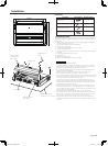
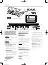
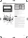
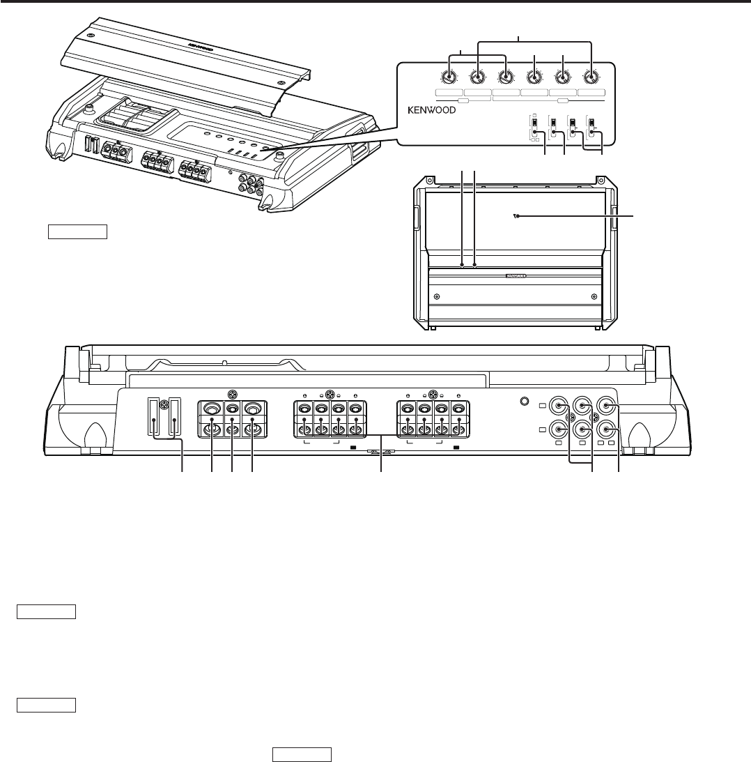
Controls
This is a 4 channel amplifier including 2 stereo
amplifiers in a body. One amplifier is referred
to as amplifier A and the other is amplifier B.
This unit is compatible with a large variety of
systems by combining the switches and functions
described in the following.
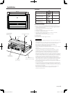
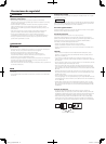
1 Fuse (40 A x 2)
NOTE
If you can’t find the specified capacity fuse at your
store etc., consult your Kenwood dealer.
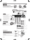
2 Battery terminal
3 Power control terminal
Controls the unit ON/OFF.
NOTE
Controls the unit power. Be sure to connect it with
all the systems.
4 Ground terminal
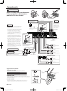
5 Speaker output terminals (A.ch/B.ch)
• Stereo Connections:
When you wish to use the unit as a stereo
amplifier, stereo connections are used.
The speakers to be connected should have an
impedance of 2 or greater. When multiple
speakers are to be connected, ensure that the
combined impedance is 2 or greater for each
channel.
• Bridged Connections:
When you wish to use the unit as a high-output
monaural amplifier, bridged connections are
used. (Make connections to the LEFT channel
9 and the RIGHT channel · SPEAKER OUTPUT
terminals.)
The speakers to be connected should have an
impedance of 4 or greater. When multiple
speakers are to be connected, ensure that the
combined impedance is 4 or greater.
6 LINE IN terminal (A.ch/B.ch)
7 LINE OUT terminal
These jacks output respectively the signals input
to amplifiers A and B.
They always output the stereo signals regardless
of the position of the "OPERATION" switch.
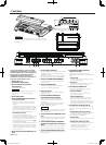
8 THERMAL MANAGEMENT indicator
Lights this indicator when the internal
temperature is high.
9 PROTECTION indicator
Lights this indicator when the protection function
is activated. (See page 2)
0 Power indicator
When the power is turned on, the Power indicator
lights.
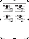
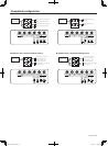
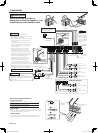
- INPUT SENSITIVITY control (A.ch/B.ch)
Set this control according to the pre-output level
of the center unit connected with this unit.
The sensitivities of amplifiers A and B can be
adjusted independently regardless of the position
of the input selector switch.
NOTE
For the pre-output level, refer to the
<Specifications> in the instruction manual of the
center unit.
= HPF/LPF FREQUENCY control (A.ch/
B.ch)
Sets the cutoff frequency when the "FILTER"
switch is set to "HPF" or "LPF".
~ BASS BOOST FREQUENCY control (B.ch)
Sets the center frequency around which the low
frequency range should be boosted.
! BASS BOOST LEVEL control (B.ch)
Sets the level by which the low frequency range
should be boosted.
@ INPUT SELECTOR switch
This switch selects the input method of the
signals to be amplified by amplifiers A and B.
• A B position:
Amplifies both of the signals input to amplifiers
A and B.
• A position:
Amplifies only signal input amplifier A with both
amplifiers A and B.
# OPERATION switch
The amplification methods of the signals input
can be selected.
• STEREO position:
The amplifier can be used as a stereo amplifier.
• MONO (Lch) position:
Amplifies the signal input from the left side
only. Set to this position and make bridged
connections to use as a high-power monaural
amplifier. (The input right signal is not output.)
$ FILTER switch (A.ch/B.ch)
This switch allows to apply high-pass or low-pass
filtering to the speaker outputs.
• HPF (High-Pass Filter) position:
The filter outputs the band of higher frequencies
than the frequency set with the "HPF
FREQUENCY" control.
• OFF position:
The entire bandwidth is output without filtering.
• LPF (Low-Pass Filter) position:
The filter outputs the band of lower frequencies
than the frequency set with the "LPF
FREQUENCY" control.
The speaker output is automatically switched to
monaural (L+R).
P.CON
SPEAKER OUTPUT
BRIDGED
FUSE
[
40A
x
2
]
GNDBATT.
+
LINE OUT
LINE IN
L
R
A A
SPEAKER OUTPUT
BRIDGED
B B
THERMAL MANAGEMENT PROTECTION
LEFT
RIGHT
A
LEFT
RIGHT
B
INPUT
SENSITIVITY
[
V
]
BASS BOOST
LEVEL
[
dB
]
HPF/LPF
FREQUENCY
[
Hz
]
0.2
[
MAX
]
0.3
0.5
200
B ch
FILTER
LPF
150
100
70
10
180
15
2
4
6
50
60
1
2
3
4
[
MIN
]
5
[
Lch
]
INPUT
SENSITIVITY
[
V
]
0.2
[
MAX
]
0.3
0.5
1
2
3
4
[
MIN
]
5
BASS BOOST
FREQUENCY
[
Hz
]
70
10040
90
80
50
60
HPF
A ch
FILTER
LPF
HPF
INPUT
SELECTOR
A
OPERATION
MONO
STEREO
OFFOFF
A ch
AB
B ch
HPF/LPF
FREQUENCY
[
Hz
]
200
150
100
70
50
60
Z
NOTE
The control panel locates under the front side cover. Remove
the cover to access to its controls for adjustment. (See page 3)
X600F_K_1English.indd 6 08.10.21 1:34:21 PM