


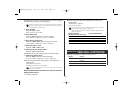
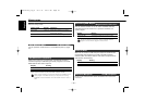
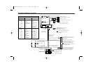
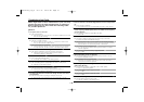

Connecting Wires to Terminals
— 43 —
TEL MUTE
EXT.CONT
P.CONT
ANT.CONT.
1
2
3
4
5
6
7
8
1
2
3
4
5
6
7
8
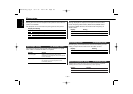
FRONT
REAR
NON
FADING
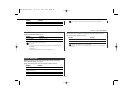
Front left output (White) 14
Front right output (Red) 13
Rear right output/
Non-fading right output (Red) 11,10
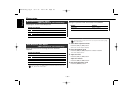
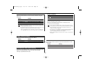
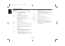
Connector Function Guide
Pin Numbers for
ISO Connectors
Cable Colour Functions
External Power
Connector
A–4
A–5
A–6
A–7
A–8
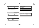
Speaker
Connector
B–1
B–2
B–3
B–4
B–5
B–6
B–7
B–8
Yellow
Blue/White
Orange/White
Red
Black
Purple
Purple/Black
Gray
Gray/Black
White
White/Black
Green
Green/Black
Battery
Power Control
Dimmer
Ignition (ACC)
Earth (Ground)
Connection
Rear Right (
+)
Rear Right (–
)
Front Right (
+)
Front Right (–)
Front Left (
+)
Front Left (–)
Rear Left (
+)
Rear Left (–)
Battery wire (Yellow) 6
Ignition wire (Red) 7
FM/AM
antenna input
2
Antenna Cord (ISO) 3
Antenna Conversion Adaptor (ISO–JASO) (Accessory3) 1
Wiring harness
(Accessory1)
5
Connect to the terminal that is
grounded when either the telephone
rings or during conversation. 24
Power control/ Motor antenna
control wire (Blue/White) 22
Connect either to the power control
terminal when using the optional
power amplifier, or to the antenna
control terminal in the vehicle. 26
A–7 Pin (Red) 8
A–4 Pin (Yellow) 9
Connector B
Fuse(10A)
4
Connector A
TEL mute wire (Brown) 21
To connect the KENWOOD
navigation system, consult your
navigation manual. 25
External amplifier
control wire
(Pink / Black) 20
To "EXT.AMP.CONT." terminal of the
amplifier having the external amp
control function. 23
Rear left output/
Non-fading left output (White) 12,29
If no connections
are made, do not let
the cable come out
from the tab. 27a
To External Display//30
Steering remote
See page 44 30
To KENWOOD disc changer/
GSM hands free unit/
External optional accessory 16
To connect these leads, refer
to the relevant instruction
manuals. 17
KDC-M7024_U.S_r2 03.1.15 10:12 AM Page 43