


2
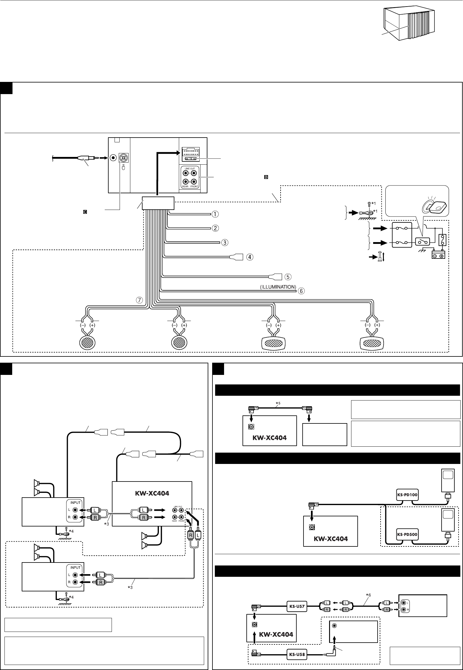
Connecting the external amplifiers
B
A
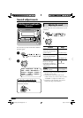
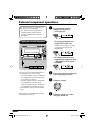
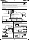
Typical Connections
Before connecting: Check the wiring in the vehicle carefully. Incorrect connection may cause serious damage to this unit.
1 Connect the colored leads of the power cord in the order specified in the illustration below.
2 Connect the antenna cord.
3 Finally connect the wiring harness to the unit.
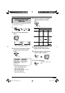
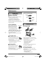
You can connect an amplifier to upgrade your car stereo system.
• Connect the remote lead (blue with white stripe) to the remote lead of the other
equipment so that it can be controlled through this unit.
• Disconnect the speakers from this unit, connect them to the amplifier. Leave
the speaker leads of this unit unused.
2
1
3
To CD changer or another external
component (see diagram
)
15 A fuse
Line out (see diagram
)
Black
Yellow
*
2
Red
Orange with white stripe
Blue with white stripe
Blue
*
1
Not included for this unit.
To metallic body or chassis of the car
To a live terminal in the fuse block connecting to the car battery
(bypassing the ignition switch) (constant 12 V)
To an accessory terminal in the fuse block
To the automatic antenna if any (250 mA max.)
*
2
Before checking the operation of this unit prior
to installation, this lead must be connected,
otherwise power cannot be turned on.
Right speaker (rear)Left speaker (rear)Right speaker (front)Left speaker (front)
White with black stripe
White Gray with black stripe Gray
Green with black stripe
Green
Purple with black stripe
Purple
To the remote lead of other equipment (200 mA max.)
To car light control switch
Ignition switch
Fuse block
*
5
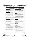
Connecting cord supplied for your CD
changer
CAUTION:
• Before connecting the CD changer, make
sure the unit is turned off.
3.5 mm stereo
mini plug
CD changer
jack
*
4
Firmly attach the ground wire to the metallic body or to the chassis of the
car—to the place uncoated with paint (if coated with paint, remove the paint
before attaching the wire). Failure to do so may cause damage to the unit.
*
3
Signal cord (not supplied for this unit)
Remote lead Y-connector (not supplied with this unit)
To the remote lead of other equipment
or automatic antenna if any
JVC Amplifier
Remote lead (Blue with white stripe)
Front
speakers
JVC Amplifier
Rear
speakers
Front speakers
Apple iPod
(separately purchased)
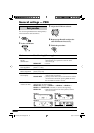
You can connect an iPod or a D. player using an interface
adapter (not supplied)—KS-PD100 (for iPod) or KS-PD500
(for D. player).
External
component
JVC CD changer
CD changer
jack
CD changer jack
*
6
Signal cord (not supplied
for this unit)
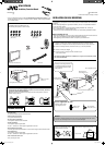
ELECTRICAL CONNECTIONS
To prevent short circuits, we recommend that you disconnect the battery’s negative terminal and make all electrical connections before installing the unit.
• Be sure to ground this unit to the car’s chassis again after installation.
Notes:
• Replace the fuse with one of the specified rating. If the fuse blows frequently, consult your JVC car audio dealer.
• If noise is a problem...
This unit incorporates a noise filter in the power circuit. However, with some vehicles, clicking or other unwanted noise may occur. If this happens, connect the unit’s rear ground terminal to the
car’s chassis using shorter and thicker cords, such as copper braiding or gauge wire. If noise still persists, consult your JVC car audio dealer.
• It is recommended to connect to the speakers with maximum power of more than 50 W (both at the rear and at the front, with an impedance of 4 Ω to 8 Ω). If the maximum power is less than
50 W, change “AMP GAIN” setting to prevent the speakers from being damaged (see page 21 of the INSTRUCTIONS).
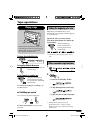
• The heat sink becomes very hot after use. Be careful not to touch it when removing this unit.
Heat sink
Rear view
JVC D. player
(separately purchased)
iPod is a trademark of Apple
Computer, Inc., registered in the
U.S. and other countries.
Connecting the external components
C
CD Changer
• Set “EXT INPUT” to “CHANGER” (see page 21 of the INSTRUCTIONS).
Apple iPod
®
or JVC D. player
External
component
• Set “EXT INPUT” to “EXT INPUT” (see page 21 of the INSTRUCTIONS).
External Component
You can connect an external component using a line input adapter, KS-U57 or KS-U58 (not supplied).
Instal2_KW-XC404[UI]f.indd 2Instal2_KW-XC404[UI]f.indd 2 8/13/05 2:39:25 PM8/13/05 2:39:25 PM