


56
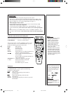
AV COMPU LINK Remote Control System
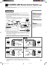
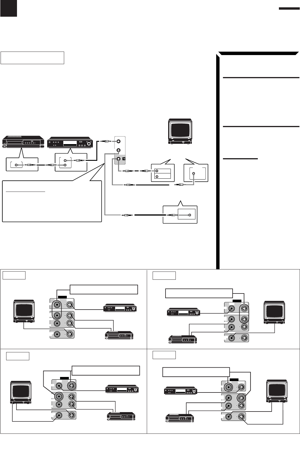
The AV COMPU LINK remote control system allows you to operate JVC video components (TV, VCR, and
DVD player) through the receiver.
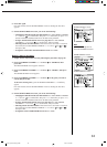
CAUTION:
The AV COMPU LINK remote
control system cannot control
the DBS tuner connected to the
TV/DBS jacks, and video
components connected to the
VIDEO and VCR2 jacks on the
receiver.
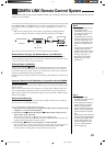
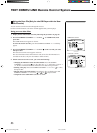
CONNECTIONS:
To use this remote control system, you need to connect the video components you
want to operate, following the procedures below.
1. If you have already plugged your VCR1 (the VCR connected to the VCR 1
jacks), DVD player, TV, and this receiver into the AC outlets, unplug their AC
power cords first.
2. Connect your VCR1, DVD player, TV, and this receiver as follows, using the
cables with the monaural mini-plugs (not supplied).
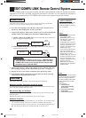
3. Connect the audio input/output jacks on VCR1, DVD player, TV, and this
receiver using the cables with RCA pin plug (see pages 9 to 10) (and a digital
cable if you want — see page 11).
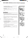
4. Connect the video input/output jacks on VCR1, DVD player, TV, and this
receiver as follows, using the cables with RCA pin plug or with S-video plug.
5. Plug the AC power cords of the components into the AC outlets.
6. When turning on the TV for the first time after the AV COMPU LINK
connection, turn the TV volume to the minimum using the TV volume control
on the TV.
Note:
When connecting either the VCR
or DVD player to this receiver,
connect it directly to the receiver
using cable with the monaural
mini-plugs.
DVD player
VCR
AV
COMPU LINK
RECEIVER/
AMP
AV
COMPU LINK
AV
COMPU LINK
VHS
AV
COMPU LINK
AV
COMPU LINK
EX
RECEIVER/AMP
(VCR)
EX
DVD
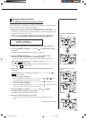
If the AV COMPU LINK terminal
on the TV is “AV COMPU LINK
EX”
If the AV COMPU LINK terminal
on the TV is “RECEIVER/AMP”
IMPORTANT:
Connect to the terminal indicated in the
illustration.
DO NOT connect to the TV terminal.
TV
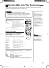
CASE1: If the components are equipped with the S-video
terminals
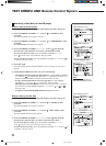
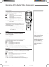
CASE3: If only the VCR is equipped with the S-video
terminal.
VIDEO
VIDEO S-VIDEO
MONITOR
OUT
VCR 1
IN
(PLAY)
OUT
(REC)
DVD
DVD
VHS
VCR
TV
To Video input 2
DVD player
DO NOT use these video terminals.
CASE4: If only the DVD player is equipped with the S-video
terminal.
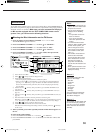
CASE2: If the components are not equipped with the S-
video terminals
VIDEO
VIDEO S-VIDEO
MONITOR
OUT
VCR 1
IN
(PLAY)
OUT
(REC)
DVD
DVD
S-VHS
VCR
TV
To Video input 1
DVD player
DO NOT use these video terminals.
To Video input 2
VIDEO
VIDEO S-VIDEO
MONITOR
OUT
VCR 1
IN
(PLAY)
OUT
(REC)
DVD
DVD
S-VHS
VCR
To Video input 1
DVD player
DO NOT use these video terminals.
VIDEO
VIDEO S-VIDEO
MONITOR
OUT
VCR 1
IN
(PLAY)
OUT
(REC)
DVD
DVD
VHS
VCR
TV
To Video input 2
DVD player
DO NOT use these video terminals.
To Video input 1
EN56_70.RX-1024V[J]/1.PM5 98.5.12, 0:44 PM56