


9
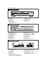
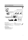
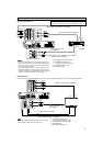
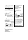
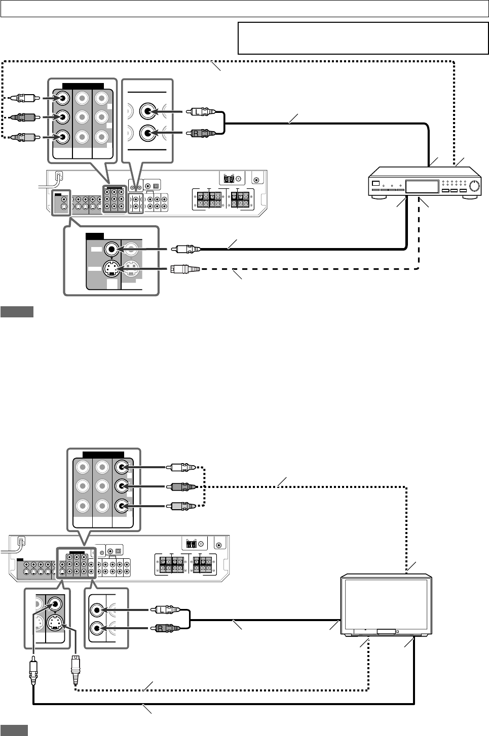
7 Connecting a TV
Connect the TV to the appropriate MONITOR OUT jacks to view the playback picture from any other connected video components.
Stereo audio cable
(not supplied)
Component video cable (not supplied)
TV
Composite video cable (not supplied)
Red
S-video cable (not supplied)
White
Å To component video input
• Connect Y, PB, and PR correctly.
ı To left/right audio channel output
Ç To S-video input
Î To composite video input
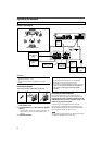
Stereo audio cable (not supplied)
Component video cable (not supplied)
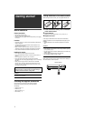
DBS tuner
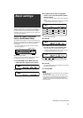
Å To left/right audio channel output
ı To component video output
• Connect Y, P
B, and PR correctly.
Ç To composite video output
Î To S-video output
White
Red
S-video cable (not supplied)
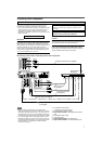
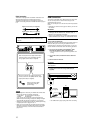
Turn off all components before making connections.
• When you connect other components, refer also to their manuals.
7 Connecting a DBS tuner
Do not connect the AC power plug to the wall outlet until all connections are completed.
Red
Green
Blue
Composite video cable
(not supplied)
Red
Green
Blue
NOTE
You can enjoy digital sound if using a digital coaxial or optical
cable. For details of digital connection, see page 10.
NOTES
• When connecting a DBS tuner to the component video input
jacks, select the component video input mode (DBS VIDEO IN)
correctly. If you do not, you cannot view the playback picture on
the TV. See page 20 for details.
• You can enjoy digital sound if using a digital coaxial or optical
cable. When shipped from the factory, the audio input mode for
a DBS tuner is set to use the digital optical terminal (DIGITAL IN
2 (DBS)). For details of digital connection, see page 10.
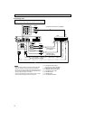
COMPONENT VIDEO
MONITOR
OUT
DVR/DVD
IN
VCR(DBS)
IN
Y
P
B
P
R
VIDEO
VC
OUT(REC)
DBS
IN
VIDEO
S-VIDEO
DBS
IN O
U
Å
ı
ÎÇ
Å
ı
ÎÇ
Y
P
B
P
R
COMPONENT VIDEO
MONITOR
OUT
DVR/DVD
IN
VCR(DBS)
IN
TV
IN
D
B
I
N
L
R
MONITOR
OUT
/
DVD
P
LAY)