


4
Installation
This unit is designed to operate on 12 V DC, NEGATIVE ground
electrical systems. If your vehicle does not have this system, a
voltage inverter is required, which can be purchased at JVC car
audio dealers.
Prepare these before installation....
Warnings
• To prevent short circuits:
– Disconnect the battery’s negative terminal and make all electrical connections before installing the unit.
– Cover the terminals of the UNUSED leads with insulating tape.
• Be sure to ground this unit to the car’s chassis again after installation.
• Replace the fuse with one of the specified rating.
• Connect speakers with a maximum power of more than 50 W (impedance of 4 Ω to 8 Ω). Otherwise,
change the <AMP GAIN> setting. (See “Menu operations” on page 3.)
• The heat sink becomes very hot after use. Be careful not to touch it when removing this unit.
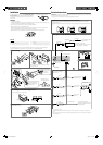
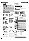
Parts List
A
Hard case .................................................................................1
B
Control panel.........................................................................1
C
Sleeve .........................................................................................1
D
Trim plate .................................................................................1
E
Power cord ..............................................................................1
F
Handles .....................................................................................2
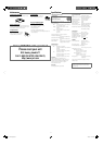
The following illustration shows a typical installation. If you have any questions or require information
regarding installation kits, consult your JVC car audio dealer or a company supplying kits.
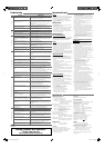
In-dash mounting
When installing the unit without using the sleeve
Removing the unit
Release the rear section first...
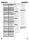
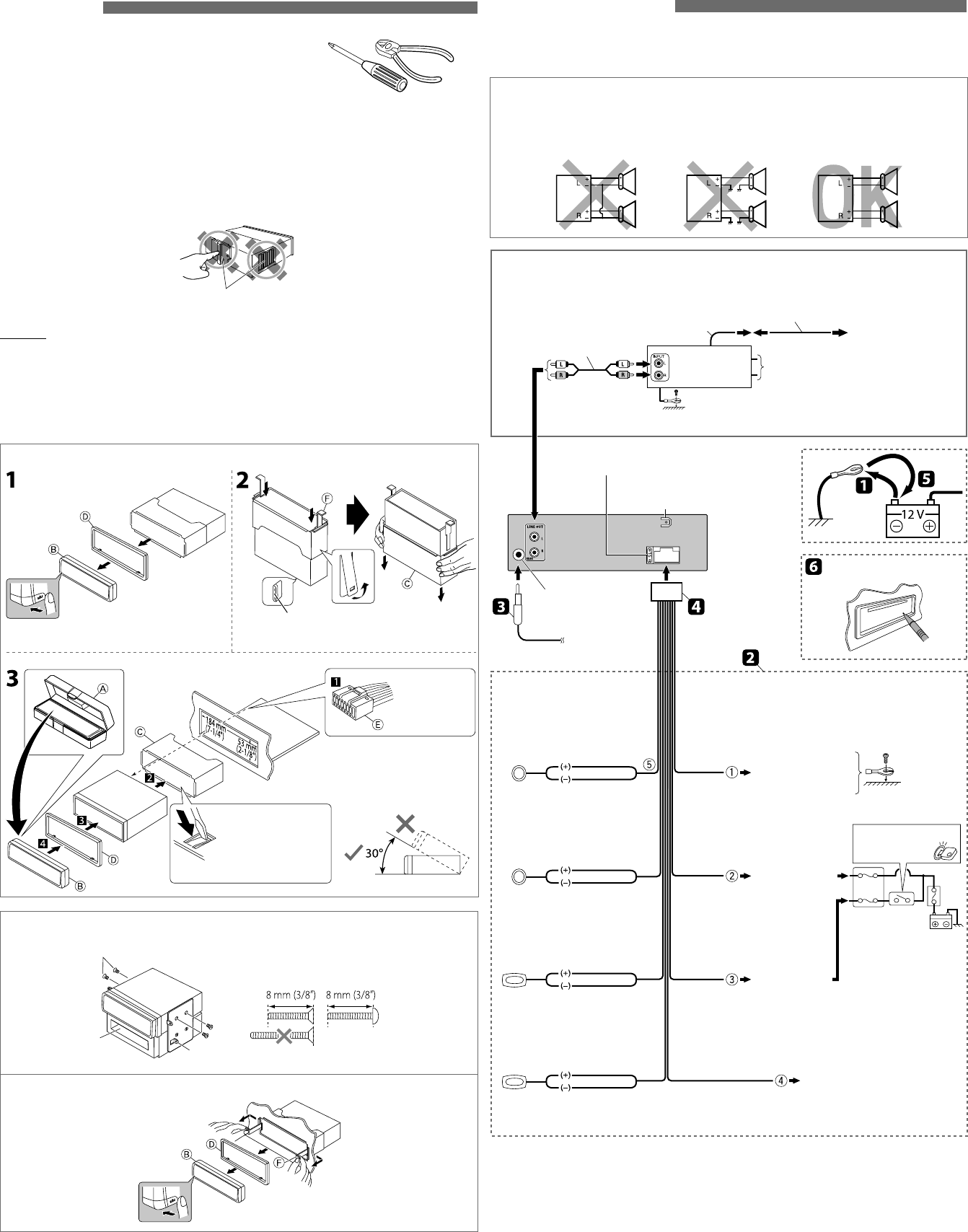
Electrical connections
IMPORTANT: A custom wiring harness (separately purchased) which is suitable for your car is recommended
for connection between the unit and your car.
• Consult your JVC car audio dealer or a company supplying kits for details.
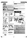
PRECAUTIONS on power supply and speaker connections
• DO NOT connect the speaker leads of the power cord to the car battery; otherwise, the unit will be
seriously damaged.
• BEFORE connecting the speaker leads of the power cord to the speakers, check the speaker wiring in your
car.
*
1
Not supplied for this unit.
*
2
Firmly attach the ground wire to the metallic body or to the chassis of the car—to the place uncoated with
paint.
*
3
Before checking the operation of this unit prior to installation, this lead must be connected, otherwise the power
cannot be turned on.
Heat sink
Bracket *
1
Pocket
Flat head screws—M5 × 8 mm (3/8”) *
1
Install the unit at an
angle of less than 30˚.
Do the required
electrical
connections.
Bend the appropriate
tabs to hold the sleeve
firmly in place.
When you stand the unit, be careful not to damage
the fuse on the rear.
Rear ground terminal
15 A fuse
Antenna input
Reset the unit
Black
Fuse block
Ignition switch
Blue (white stripe)
Red
Yellow *
3
To the metallic body
or chassis of the car
To an accessory
terminal
To a live terminal
(constant 12 V)
To the remote lead of other
equipment or automatic antenna if
any (200 mA max.)
White
White (black stripe)
Gray
Gray (black stripe)
Green
Green (black stripe)
Purple
Purple (black stripe)
Front speaker
(left)
Front speaker
(right)
Rear speaker
(left)
Rear speaker
(right)
Signal cord *
1
Y-connector *
1
Remote lead
To the blue (white stripe)
lead of the unit
Rear speakers or subwoofer
Make the <L/O MODE> setting accordingly.
(See “Menu operations” on page 3.)
JVC Amplifier
Connecting the external amplifier or subwoofer
*
2
Connect only the front speakers
if your speaker system is two-
speaker system.
*
1
*
1
EN_KD-R418[J]f.indd 4EN_KD-R418[J]f.indd 4 10/23/09 2:30:41 PM10/23/09 2:30:41 PM