


4
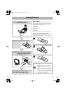
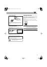
Step
3
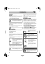
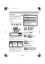
: Hook Up
If you need more detailed information, see page 6.
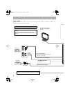
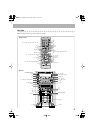
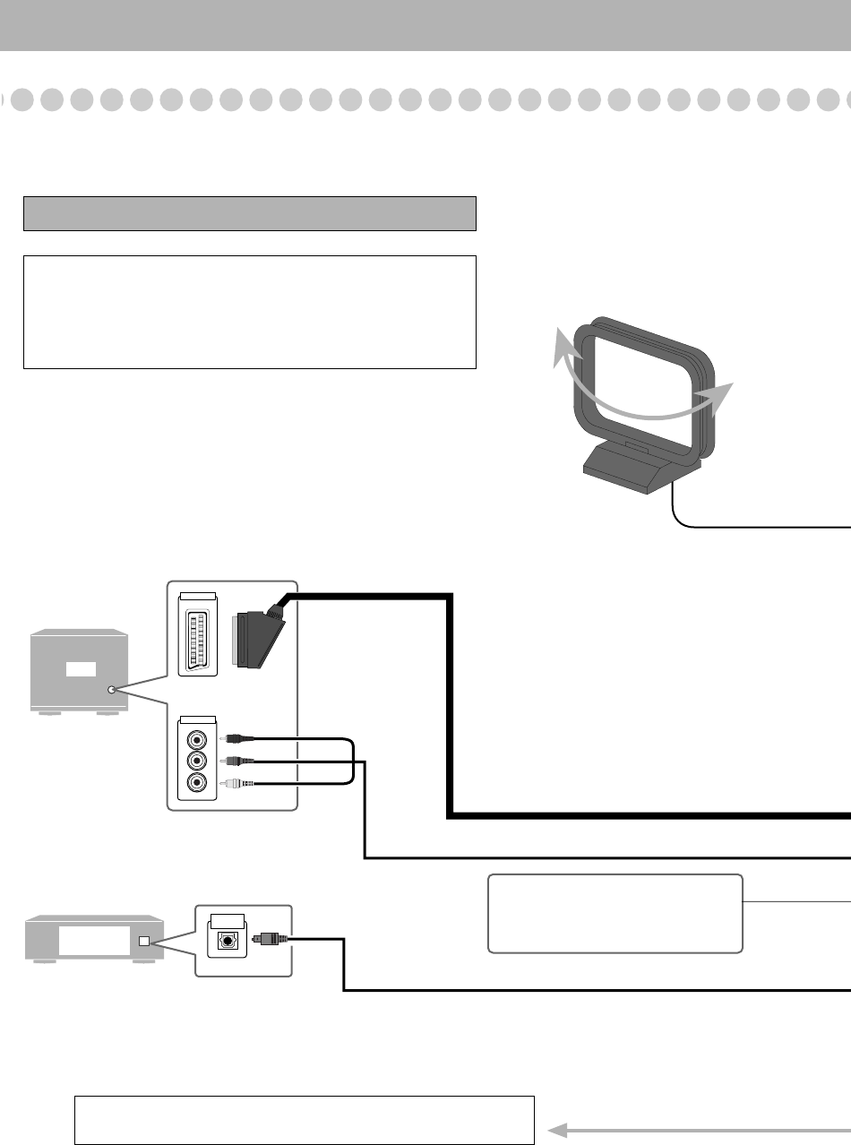
TV
VIDEO INPUT
Digital audio
equipment
OPTICAL
DIGITAL IN
VIDEO INPUT
Y
P
B
PR
Turn the power off to all components before connections.
Illustrations of the input/output terminals below are typical
examples.
When you connect other components, refer also to their
manuals since the terminal names actually printed on the rear
may vary.
Optical digital cord (not supplied)
Component video cord (not supplied)
AM loop antenna (supplied)
Turn it until the best reception is
obtained.
Red
Blue
Green
To a wall outlet
Plug the AC power cord only after all connections are complete.
MD recorder,
Amplifier etc.
SCART cord (not supplied)
• This connection only sends the video signals
(Composite, Y/C, or RGB).
AV COMPU LINK terminal
• For future use.
HX-GD8.book Page 4 Friday, March 19, 2004 11:27AM