


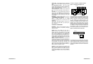
Power Cord – Plug the power cord into an AC wall
outlet or other AC outlet capable of supplying at least 200
Watts.
Level Control/Power Switch – Turns the AC supply
completely OFF or balances the loudness of the Subwoofer
relative to the Front speakers and compensates for room
effects on the Subwoofer’s output.
Power indicator LED – This LED is unlit when the AC
power switch is OFF. It glows green when the Subwoofer is
on.
FUSE 250V 1A – This fuse protects against internal and
external faults. If the POWER switch is ON and the power
indicator LED is unlit, unplug the power cord from the AC
outlet and check the fuse by unscrewing the center piece
from the holder.
IMPORTANT – If the fuse is blown, replace it only with a
fuse of the same type and current rating.
L, R SPEAKER-IN and OUT Terminals – See Connection
Option 1. These terminals are for making
connections using speaker wire. If you use this option, do not
use Option 2.
LINE In Jack – See Connection Option 2. This jack is for
input connection using audio cables. If you use this option,
do not use Option 1.
CONNECTING THE SUBWOOFER
IMPORTANT – When you make connections, make sure
that the power switches of all components, including the
Subwoofer, are OFF.
Speaker wire Typical speaker wire has a pair of
separate conductors with insulating jackets that are
molded together. We recommend that you use 16-gauge
speaker wire for hooking your Receiver to your Front speak-
ers. To make connections to the Subwoofer in
parallel with the Front speakers easier, the speaker wire con-
necting the Receiver to the Subwoofer can be smaller (high-
er gauge number), since the Subwoofer does not draw large
amounts of power through these wires.
Polarity All speakers in a system must be connected with
the same polarity. Speaker wire is marked for polarity so that
you can identify which wire in the pair is which. Polarity is
shown by a color stripe on the insulation, by ridges molded
into the insulation, or by the colors of the wires – one
copper and one silver. Strip the insulation from speaker wire
ends to reveal the bare conductors before connecting to
Receiver, Subwoofer or Speaker terminals.
IMPORTANT – Always connect the red (+) terminal on the
Receiver to the red (+) terminal on the Subwoofer, and the
black (-) terminal on the Receiver to the black (-) terminal on
the Subwoofer. The same is true for hooking the Receiver
outputs to the Front speakers: red (+) to red (+), and black (-)
to black (-).
IMPORTANT: Use Option 1 or Option 2 (not both).
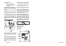
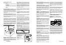
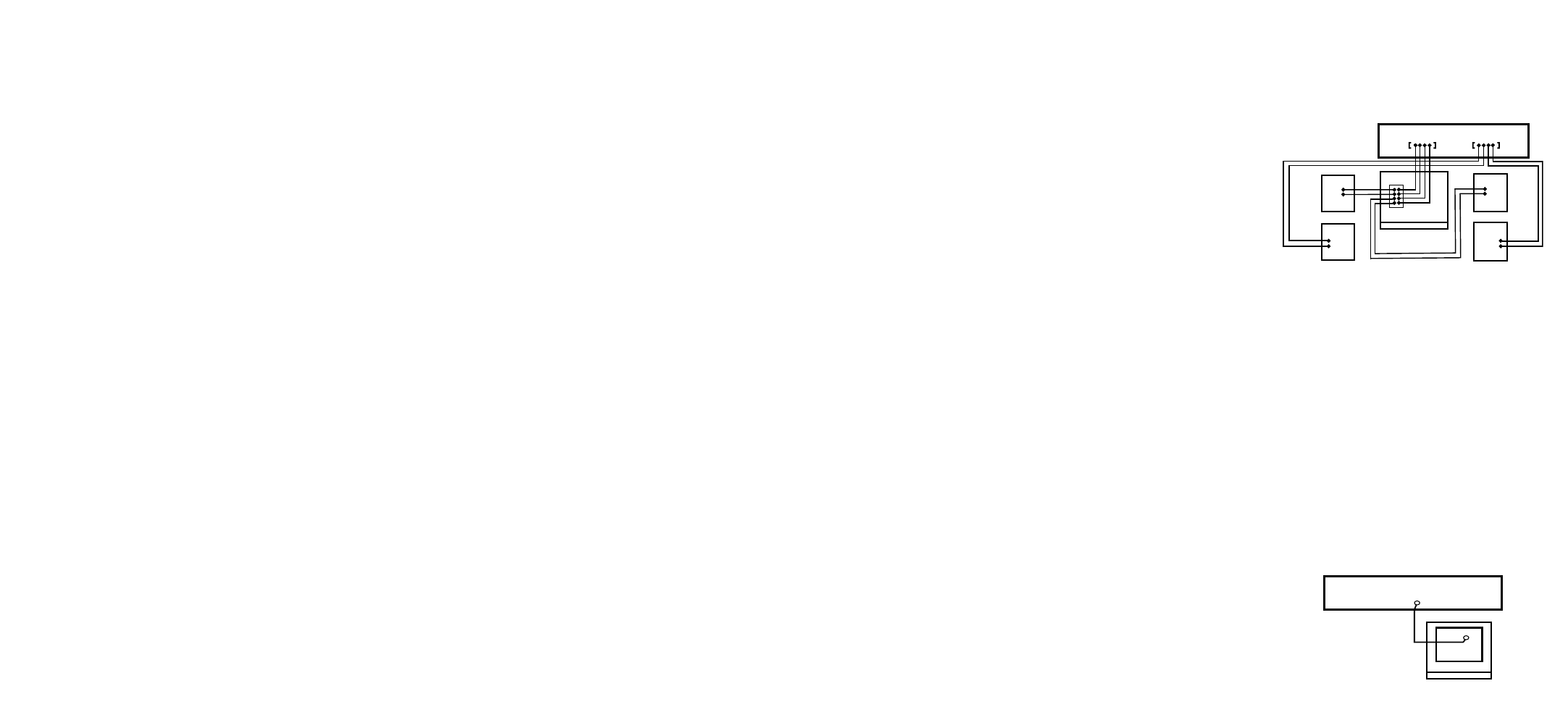
Option 1 – Connection with speaker wire
Connect speaker wires from the Receiver’s front left and
right speaker outputs to the Subwoofer’s Speaker Level-In
connections. Connect left channel to left input and right
channel to right input. You have the option of connecting
your main speakers to the speaker B outputs on your
Receiver, if it is so equipped. You also have the option of con-
necting your main speakers using the connections on the
Subwoofer. This will pass the audio signal to your main
speakers, except the low bass which will be produced by
your Subwoofer. To use this connection option, connect your
main speakers to the right and left outputs on the Subwoofer
(see illustration for Option 1). Be sure you take care to
maintain proper signal polarity, red to red and black to black.
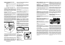
Option 2 – Connection with an audio cable
This connection uses a low level sub signal. This is usually
found on Receivers equipped with Dolby Digital™ decoding.
Locate the Subwoofer output on the back of your receiver.
Using a standard RCA cable connect the Subwoofer output
on the back of your Receiver to the Line-In on the back of the
Subwoofer.
SUBWOOFER
FRONT
LEFT
SPEAKER
FRONT
RIGHT
SPEAKER
REAR
LEFT
SPEAKER
REAR
RIGHT
SPEAKER
RECEIVER
Front
Speaker Outputs
Rear
Speaker Outputs
Speaker Level
Out
In
RECEIVER
SUBWOOFER
Subwoofer
Output
Line In
JHT525 MANUAL 3JHT525 MANUAL 14