


For installations in new construction
p
rojects, use the JBL P81/P941 In-Wall
R
ough-In Bracket, which should be
installed by a professional. Refer to the
JBL P81/P941 In-Wall Rough-In Bracket
Installation Instructions for more infor-
m
ation.
The JBL P81 and P941 in-wall speakers
were designed to be easily installed
into existing walls. It is recommended
t
hat they be professionally installed.
The following tools are required for
installation:
•
(
4) Allen-head screws (included)
•
5/32-inch Allen key (included)
•
1/16-inch Allen key (included)
•
cardboard installation template
(included)
•
pencil
•
Phillips-head screwdriver
•
measuring tape
•
utility knife
•
carpenter’s level
•
flat-blade screwdriver
•
stud finder
To Install the P81/P941:
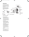
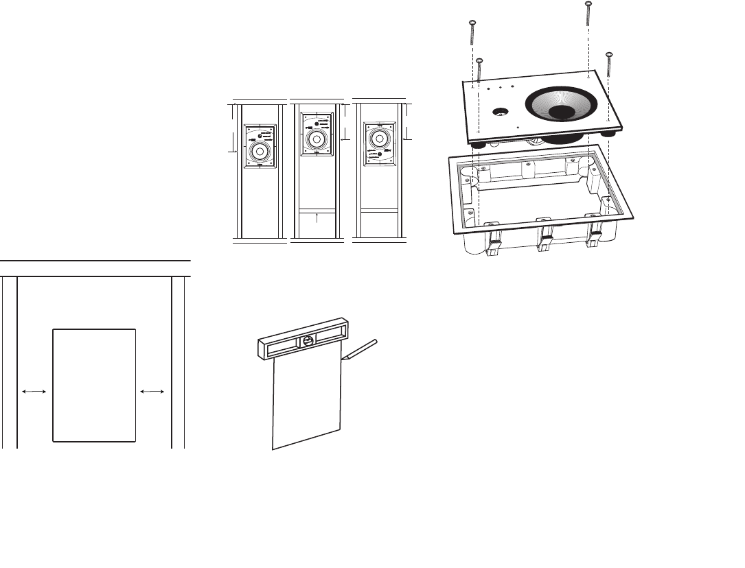
1. Locate the wall studs.
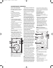
2. Use the supplied template to trace an
outline to mark the desired location
to mount the speaker system. Use
caution to cut the hole approximately
centered between wall studs, allow-
ing at least 1 inch between the
cutout and wall studs, as shown in
Figure 9. Use a carpenter’s level to
ensure a level measurement.
Figure 9: Use W
all T
emplate
NOTES:
•
T
he height of the woofer within the
stud bay relative to the entire height
of the bay is critical because of
standing waves within the cavity.
•
Before installation, determine the
height of the cavity. (There might be a
fire block that makes it shorter than
the entire height from the floor to the
c
eiling.) Avoid placing the woofer at
the very top or bottom of the stud bay,
as this would cause a serious cancel-
lation of low frequency output.
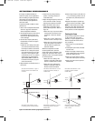
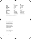
•
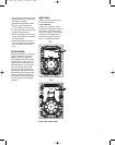
The ideal location for the woofer
(whether the speaker is mounted
upright or inverted) is at the one-third
distance point, as shown in example
A
of Figure 10. If that is not feasible,
then two-fifths, or one-fifth of the
height are the next best alternatives.
The least desirable position to place
the woofer is at one-half or one-
fourth of the height. If a fire block
is completely dividing the bay, the
measurement would be from the fire
block – not the floor or ceiling – as
shown in example B of Figure 10.
Example C shows an inverted speaker
placement.
Figure 10: Ideal Height of Woofer
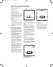
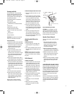
Figure 11: Cut Wall Opening
3. With a utility knife, cut the wall
o
pening, as shown in Figure 11.
•
Use caution not to cut into any
electrical wiring or plumbing. Run
the wiring from your system to the
h
ole. (Be sure to comply with local
w
iring codes.)
•
The measurements of the open-
ing(s) required to mount the JBL
i
n-wall frames are listed below:
•
JBL P81
Width: 10-1/2 inches (267mm)
Height: 14-7/8 inches (378mm)
•
JBL P941
Width: 12-1/2 inches (318mm)
Height: 19-1/8 inches (486mm)
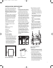
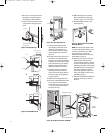
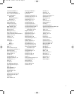
4. The speakers are shipped with the
baffle assembly attached to the
mounting frame at its four corners.
Unscrew the four screws and care-
fully lift the baffle assembly out of
the mounting frame, as shown in
Figure 12.
Figure 12: Remove Baffle From
Mounting Frame
5. (Optional) It is recommended that the
frame be painted before it is mounted.
For instructions on painting the frame
and grille, refer to page 12.
6. The mounting frame has spring-
loaded clamps around its perimeter,
which are designed to fold shut as
the mounting frame is placed into the
wall opening and spring open once
inside, anchoring the mounting frame
in the wall opening. See Figures 13
and 14. Loosen all clamp screws until
the clamps are fully extended.
Baffle
Mounting Frame
Figure 12:
Remove Baffle from Mounting Frame
Carpenter's Level
Utility Knife
Figure 10: Cut wall opening
Place Woofer
a
t 1/3 the
height of
Stud Bay
1/3 the height
of Stud Bay
(measured
from the
Fire Block)
1/3 the height
of Stud Bay
(measured
from the
Fire Block)
Fire Block
1/3 of
Height
1/3 of
Height
1/3 of
Height
C
BA
F
igure 11: Ideal Height of Woofer
At least
1-inch
At least
1-inch
Figure 9: Use wall template
9
I
NSTALLATION INSTRUCTIONS
P81, P941 OM 2/18/05 10:55 AM Page 9