


15
I
NDEX
2-Channel Installations 8
5.1-Channel Installations 8
6.1-/7.1-Channel Installations 8
A
bout the P81/P941 4
H
ighlights 4
Product Registration 4
Unpacking 5
Allen Key 5, 9, 10, 13
Aluminum Ring 4, 6
A
mplifier Power Range
Recommended 14
Baffle Assembly 9, 10
Baffle, Centering of 10
Banana Plugs 11
Binding Post 4, 7, 11
Butyl Rubber Surround 6
Carbon Composite Aluminum (CCA) 6
Caution 3, 8, 11, 13
Clamps 10, 13
Compression 4, 6
Cones 4, 6
Connections 4
Input 7
Making 11
Connectors 11
Depth 14
Distortion, Reducing 4, 6
Documentation Conventions 3
Dome (see Cones)
Driver Complement 6–7
Dynamic Range 4
Ferrofluid 6
Fiberglass Bobbin 6, 7
Fiberglass Insulation 5, 10
Filter Network 7, 11
Filters 4, 7
Fire Block 4
Flux-Stabilization Ring 4, 6
Frame Alignment Tool 5, 10
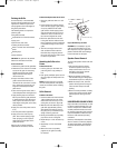
Grille 13
Grille Installation 13
Grille Removal 13
Heat Dissipation 4, 6
Height 9, 14
High-Frequency Level 4, 6, 12
High-Frequency T
ilt 4, 6, 12
Highlights 4
Home Theater 4, 8
Ideal Height of Woofer 9
In-Wall Placement 9
Input Panel 7
I
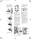
nstallation Considerations 8
I
nstallation Instructions 9–10
Inverted Speaker 9, 12
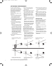
Listener Axis 4, 6, 7, 12
Listening Room 8, 12
Loudspeaker Cable 11
L
oudspeaker Overview 6
Loudspeaker Placement 8, 9, 12
Loudspeaker Volume Levels 13
Low-Frequency Boundary
Compensation 4, 6, 12
Magnetic Shielding 4
Making Connections 11
Maximum Wire Gauge 11
Midrange 4, 6–7, 14
Mounting Frame 9–10
Neodymium Magnets 4, 6–7
Nomex Spiders 4
Nominal Impedance 14
Obtaining Service 14
On-Axis Response 4, 6, 12
Optimizing Performance 12
Organic Ceramic Composite
Cone Material 4, 6
Packing Carton 5, 14
Packing Materials 5, 14
Paint Mask 5, 13
Painting the Frame 12
Painting the Grille 13
Polarity 11
Primary Listening Position 8, 12
Product Registration 4
Rear Speakers 8
Room Placement 8
Rough-In Bracket 4, 9
Scrim Cloth 5, 13
Sensitivity 14
Shipping 5, 14
Spacer Shim 5, 10
S
peaker Frame Removal 13
S
peaker Wire 10, 11
Specifications 14
Spider 4
Steel-Shield Cup 4
Stereo Imaging 11
S
tud Bay 9
Surround Channels 8
Symmetrical Field Geometry (SFG
™
) 6, 7
Terminal Connectors 7, 11
Timbre 4, 12
Titanium Domes 4, 6
Transducers 4, 6
Tweeter 4, 6, 12, 14
UL Listed 11
Unpacking 5
Vented Center Pole 6
Voice Coil 4, 6–7
Volume Levels 12, 13
Wall Cutout Height 9, 14
Wall Cutout Width 9, 14
Wall Openings 9
Wall Studs 9
Wall Template 5, 9
Web Site 14
Width 13, 14
Wire Connections 11
Wire Gauge 11
Wire Resistance 11
Wiring Codes 11
W
oofer 4, 6, 14
Woofer Height 9
P81, P941 OM 2/18/05 10:55 AM Page 15