


P81/P941 DRIVER COMPLEMENT
T
he numbers in Figure 3 correspond to
the numbered items in this section.
1. Tweeter
•
1-inch (25mm) titanium dome
•
Underhung with copper-clad alu-
minum wire for low distortion
•
Ferrofluid for high-power handling
with reduced compression
2. Woofer
•
7-1/2-inch (191mm)/9-inch (229mm)
cones constructed with Organic
Ceramic Composite cone material for
low distortion
•
T
rue pistonic operation for increased
freedom from coloration
•
Symmetrical Field Geometry (SFG
™
)
design for low overall distortion
•
Aluminum ring for flux stabilization
greatly reduces distortion at low fre-
quencies
•
Butyl rubber surround for large, linear
excursion capabilities
•
Carbon composite aluminum (CCA)
flatwire voice coil wound on a 1-1/2-
inch (38mm) fiberglass bobbin for low
mass and higher power handling
•
Vented center pole for improved heat
dissipation and low compression
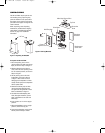
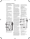
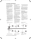
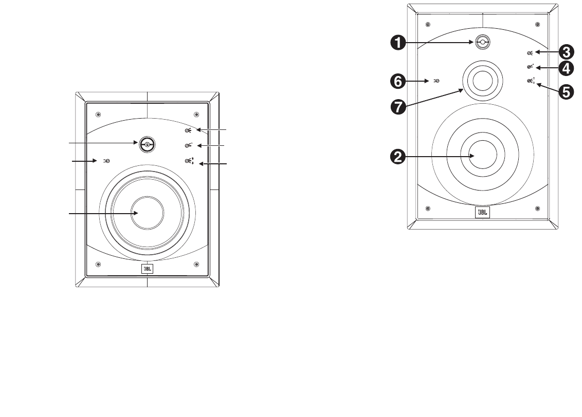
The numbers in Figure 3 correspond to the
numbered items in the Driver Complement
section.
Figure 3: P81 Speaker (Front View)
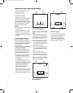
3. High-Frequency Level (dB) Control
P
rovides a shift in the output level of
the tweeter or overall high-frequency
response (active above approximately
2.5kHz). The options are –1dB, 0dB
a
nd +1dB.
4. High-Frequency Tilt Control
Adds a ”tilt“ to the high-frequency
r
esponse. The tilt will become active
above approximately 8kHz (depart
from nominally flat response) and will
increase to 3dB – 4dB at 20kHz. This
will offer an improved high-frequency
response for installations where the
primary listening position is located
significantly off the tweeter axis (for an
effect almost like adding ”toe in“ towards
the listening position). The added
high-
frequency contour helps to offset per-
ceived reduction of high-frequency
response for off-axis listeners due to
the increase in directivity of the system
(tweeter beaming) above 8kHz.
5. Listener Axis Control
All loudspeakers sound best when the
listener is positioned at optimal angles
relative to the speaker placement. This
is a fixed angle for most loudspeakers,
but the P81 and P941 provide compen-
sation for much greater placement
flexibility. The listener axis control,
used in conjunction with the placement
of the speaker, can obtain excellent
results in a very wide range of circum-
stances. This control optimizes system
response for installations in which the
listening positions are lower than,
higher than, or directly level with the
tweeter. This switch will be active
in the network transition regions
between the woofer and tweeter
(in the P81) and the midrange and
tweeter (in the P941).
•
Select the “high” (up arrow) setting
if the speaker is mounted so that the
listener is at tweeter level or above.
•
Select the “on axis” setting if the
listener position is located directly
on axis with the tweeter level.
•
Select the “low” (down arrow) set-
ting if the speaker is mounted so that
the listener is below tweeter level.
NOTE: In some circumstances, such
as when the speaker is to be mounted
high on the wall towards the ceiling, it
may be desired to invert the speaker in
order to place the tweeter axis closer
to the listener’s ear level. The Listener
Axis Control will also optimize these
inverted speaker installations. Refer to
t
he Notes on page 9 and the Optimizing
P
erformance (page 12) section for addi-
tional information.
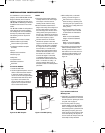
6. Low-Frequency Boundary
C
ompensation Control
Compensates for less-than-ideal
speaker placement near adjacent walls
or boundaries.
•
Select the “off” setting if the speaker
is mounted at least 4 feet away from
adjacent walls or boundaries.
•
S
elect the “on” position if the
speaker is less than 4 feet from one
(or possibly two) or more adjacent
walls or boundaries. In the ”on“
position, system output is reduced
below approximately 400Hz to offset
the increased low-frequency support,
due to the boundary.
NOTE: Refer to the Optimizing
Performance section on page 12 for
more information about the front-panel
controls.
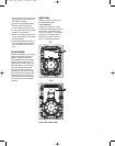
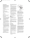
The numbers in Figure 4 correspond to the
numbered items in the Driver Complement
section.
Figure 4: P941 Speaker (Front View)
7. Midrange (P941 Only)
•
3-1/2-inch (89mm) cone constructed
with Organic Ceramic Composite
material
•
Die-cast basket to eliminate col-
oration from resonances
•
True pistonic operation for increased
freedom from coloration
6
L
OUDSPEAKER OVERVIEW
The numbers in Figure 3 correspond
to the numbered items in the Driver
Complement section.
¡
™
£
¢
∞
§
Figure 3: P81 Speaker (Front View)
on
off
Low Frequency
Boundary
Compensation
High Frequency Level (dB)
Listener Axis
High Frequency Tilt
on axis
0
+1
0
–1
The numbers in Figure 4 correspond
to the numbered items in the Driver
Complement section.
Figure 4: P941 Speaker (Front View)
on
o
ff
Low Frequency
Boundary
Compensation
High Frequency Level (dB)
L
istener Axis
H
igh Frequency Tilt
o
n axis
0
+1
0
–1
P81, P941 OM 2/18/05 10:55 AM Page 6