


4
Bridged Mode OperationWith the amplifier in bridged mono mode and driving a high-
power subwoofer system, the MPC-X100 can be used as a subwoofer filter, taking full-range
audio from Channel 1s input and sending on a 100 Hz low-pass signal to the amplifier
circuitry. For correct operation, bypass Channel 2 on the MPC-X100 board and use only
Channel 1s input and processing.
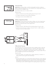
Bypassing the filters
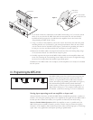
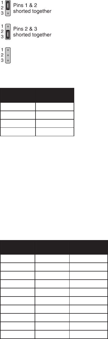
To completely bypass the filter circuitry of a channel, set the jumpers on both Jx01 and Jx02
across pins 1 and 2, which are the upper two pins on their headers (see Figure 4). Note: If
you neglect to place jumpers on either header, no signal will pass on that channel. To
bypass Channel 2 for bridged mode operation, set the jumpers on headers J201 and J202
across pins 1 and 2.
Channel 1 (subwoofer): Programming the subsonic (high-pass) filter
Bypass/enable headerTo use the subwoofer channels high-pass subsonic filter, set the
jumper on header J102 across pins 2 and 3, which are the lower two pins. If you do not want
any subsonic filtering, bypass the filter by setting the jumper across pins 1 and 2. Note:
Subwoofers tend to sound best when used with suitable filtering, which prevents the
amplifier and speaker from wasting power trying to reproduce frequencies that are too
low. For best performance it is recommended that you bypass the high-pass filter only
if there is suitable filtering elsewhere in the audio signal path.
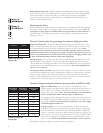
Setting frequencyTo set the corner frequency (at which the output is 6 dB down) of the
high-pass filter, set switch S102 to ×1 (down) and choose the appropriate resistor network
value for RN104. Use the high-pass table to select the right combination. See the appendix of
this manual for keys to identifying the correct resistor network. Note: Switch S101 should
also be set to ×1 (down).
Inserting the resistor networkThe factory preset frequency is 20 Hz. If there is a resistor
network already installed in the socket, carefully pull it straight out. Insert the pins of the new
resistor network into the socket holes and carefully press the network into the socket. Be
careful to avoid bending the pins of the resistor network. Orientation of the resistor network
is unimportant, as long as all 8 pins are well seated in the socket.
Channel 2: Programming the ultrasonic (low-pass) filter and CD horn EQ
Bypass/enable headerTo use the low-pass ultrasonic filter, set the
jumper on J201 across pins 2 and 3, which are the lower two pins. But if you
do not wish to use the low-pass filter and want to bypass it instead, set the
jumper across pins 1 and 2. Note: Ultrasonic filtering is recommended to
reduce susceptibility to RF and other types of interference.
To engage the 100 Hz high-pass filter, place a jumper across pins 2 and 3 of
header J202. To bypass the filter for full-range audio, place the jumper across
pins 1 and 2. Note: if you need CD horn equalization, you must engage
the 100 Hz high-pass filter also.
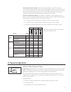
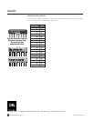
Setting frequencyTo set the corner frequency (at which the output is
6dB down) of the low-pass ultrasonic filter section, choose the appropriate
resistor network value and switch setting for RN202 and S201, respectively.
(Sx01 is a ×10 range switch. In its upper position, the frequency range is ×10;
in the lower it is ×1.) Use the low-pass table at left to select the right combi-
nation. See the appendix of this manual for keys to identifying the correct
resistor network. Note: Switch S202 should always be set to ×1 (down).
The high-pass frequency is fixed at 100 Hz and cannot be changed.
ni102ShctiwS
noitisop"1×"
ni102ShctiwS
noitisop"01×"
krowtenrotsiseR
202NRni
•
zH008K021
•
zH0001K28
•
zH0021K86
•
zH0061K65
•
zH0002K74
zH052zH0052K33
zH005zH0005K81
zH008zH0008K21
zH0061zH00061K6.5
zH0002zH00002K7.4
ni201ShctiwS
noitisop"1×"
krowtenrotsiseR
401NRni
zH02K021
zH03K28
zH04K65
zH05K74
Ultrasonic (low-pass) filter
frequency table
Subsonic (high-pass) filter
frequency table
Figure 4