


3
NOISE SHIELD
TA B
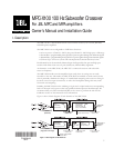
8 If you need to make any adjustments to the MPC-X100 settings or if you need to record
them, do so now, because the MPC-X100 will be inaccessible once the noise shield is
installed and the input panel is re-installed into the amplifier chassis. See Section III,
Programming the MPC-X100, below.
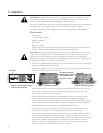
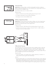
9 Using a ¼-inch (6.3 mm) nutdriver, remove the outer 4-40 nut from the stud in the panel
mounting bracket, next to Channel 1s gain control potentiometer. Place the noise shield
over the circuit board of the MPC-X100 (Figure 3) and bend the grounding tab down so
its hole goes over the stud. Re-install the nut, and tighten it securely (Figure 4).
10 Reconnect the ribbon cable to the input board connector. Press the locking clamp wings
of the connector closed. You will feel them snap into place.
11 Carefully reposition the input board/MPC-X100 assembly into the amplifier chassis and
secure it by fastening the two mounting screws. Make sure the screws are tightened snugly,
but do not over-torque them. Re-install the upper blank panel.
Installation of the MPC-X100 is now complete, and the amplifier is now ready to be installed
into the system.
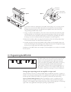
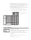
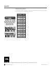
III. Programming the MPC-X100
The MPC-X100 is preset for a 100 Hz crossover point; this
frequency cannot be changed. The circuit board has four
switches, six 3-pin headers, and two SIP resistor network
sockets, all used for programming the module (see Figure 3).
The numerical designations identify which channel the
switch, header, or socket is part of: those designated by a 3-
digit number starting in a 1 (for example, headers J101) are
for Channel 1, while those starting in a 2 are for Channel 2.
Setting input operating mode on amplifier or input card
The input board or accessory on which the MPC-X100 is installed has provisionsswitches or
headersfor setting the operating mode of the amplifier. In the signal flow, the MPC-X100 is
located after these switches or headers, so its operation is affected by the mode setting.
Stereo or Parallel Mode OperationWith the amplifier in stereo or parallel mode, the
MPC-X100 operates normally: Channel 1 provides a 100 Hz low-pass subwoofer signal to
Channel 1 of the amplifier, while Channel 2 provides either a 100 Hz high-pass or a full-range
signal. Most 2-way applications will require operating in parallel mode.
Figure 3. The MPC-X100’s switches, jumpers, and resistor networks.
#4-40 NUT
CH.1 GAIN CONTROL
NOISE SHIELD
INPUT PANEL PCB
Figure 3 Figure 4