


2
II. Installation
CAUTION: The MPC-X100 contains active components which can be damaged by electro-
static discharge (ESD). Be sure to practice standard ESD precautions, and always ground
yourself and your workstation before handling exposed circuit cards.
Installing the MPC-X100 requires PC board soldering skills. Only qualified service technicians
should attempt it. Any authorized JBL service center can perform the installation.
The MPC-X100 installs on the amplifier input board of any JBL MPA or MPC amplifier.
Tools needed:
Soldering iron
¼-inch (6.3 mm) nutdriver
Phillips screwdriver
Wire cutters
Rosin-core solder
Desoldering iron or other suitable desoldering equipment (Do not use desoldering braid; it can
damage the solder pads on the input board and might not remove solder adequately.)
CAUTION: Preparing the input board for installation of the MPC-X100 involves removing
solder from feed-through holes on a 2-sided circuit board. Excessive heat can damage the
solder pads you will be working on. Proper equipment and experience with desoldering
delicate PC board circuitry is essential to successfully perform the procedure. Damage caused
by improper installation is not covered under warranty.
1 Turn off the amplifier and disconnect the AC power cord from the AC source. Disconnect
all cables from the amplifiers input panel.
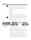
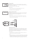
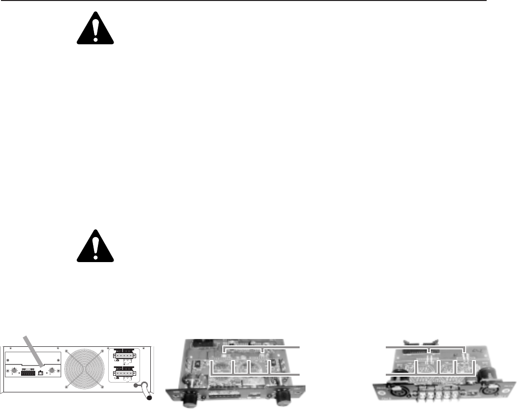
2 Position the amplifier so the rear of the chassis is facing you. The input panel is located on
the left side of the rear panel. See Figure 2a.
3 Locate and remove the screws securing both the upper blank and the lower input panels to
the rear side of the chassis (2 screws on each mini panel). The upper blank panel will
simply drop off when its screws are removed.
4 Gently pull the lower input panel out from the amplifier. Once it is removed, you will
notice a ribbon cable connecting the input PC board to the amplifier. Disengage the
locking wing clamps on the ribbon header and carefully remove the ribbon head from the
socket on the board. Now the input panel assembly is completely free from the amplifier.
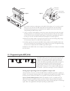
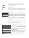
5 Desolder and remove the wire jumper pairs indicated in Figure 2b or 2c.
6 Under where the jumpers were located, youll find two rows of solder pad holesone
with 10 holes and another with 12 holes. Remove the solder from all 22 holes.
7 With the input panel facing you and the component side of the MPC-X100 board facing
away from you, carefully insert the header pins of the MPC-X100 fully into the socket
holes. Turn the assembly over and solder the MPC-X100 in place. Make sure all the header
pins are well soldered. Visually inspect for cold solder joints and verify that you have
sufficient clearance to re-install the ribbon connector on the top side of the assembly.
Finish by trimming the MPC-X100 header pins as required.
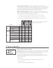
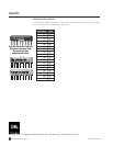
CH1
CH2
CH1
CH2
BRIDGE
MONO
BRIDGE
MONO
LOW IMPEDANCE
LOW IMPEDANCE
DIR. OUTPUT
DIR. OUTPUT
ISOL.OUTPUT
ISOL.OUTPUT
AUDIO TRANSFORMER
AUDIO TRANSFORMER
70V
70V
25V
25V
100V
100V
070100
070100
0
0
-dB -dB
10 10
88
66
44
22
24
24
18 18
14
14
STEREO
12
12
CH2 INPUT CH1
CH 2 CH 1
PARALLEL BRIDGE LEVELLEVEL
GROUND
INPUT
Figure 2a. The input panel’s location
on the rear panel of the amp
Figure 2b. The input panel (MPC)
Input panel
Figure 2c. The input panel (MPA)
Wire jumpers: W303/304 and
W403/404 (MPC); or W305/
306 and W405/W406 (MPA)
Solder holes for MPC-XU