


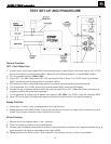
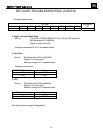
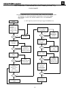
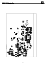
CAUTION : SPEAKER OUTPUT IS FLOATING AND IS NOT PROTECTED AGAINST A SHORT
TO GROUND. ALL TEST INSTRUMENTS CONNECTED TO THE OUTPUT MUST
BE FLOATING. ATTACH THE SCOPE PROBE TIP TO S - and REFERENCE
LEAD TO S+.
(A 10mV signal may need from the input to trigger the Switch turn on)
no
no
yes
yes
no
no
yes
yes
no
no
yes
yes
no
no
yes
yes
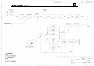
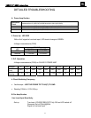
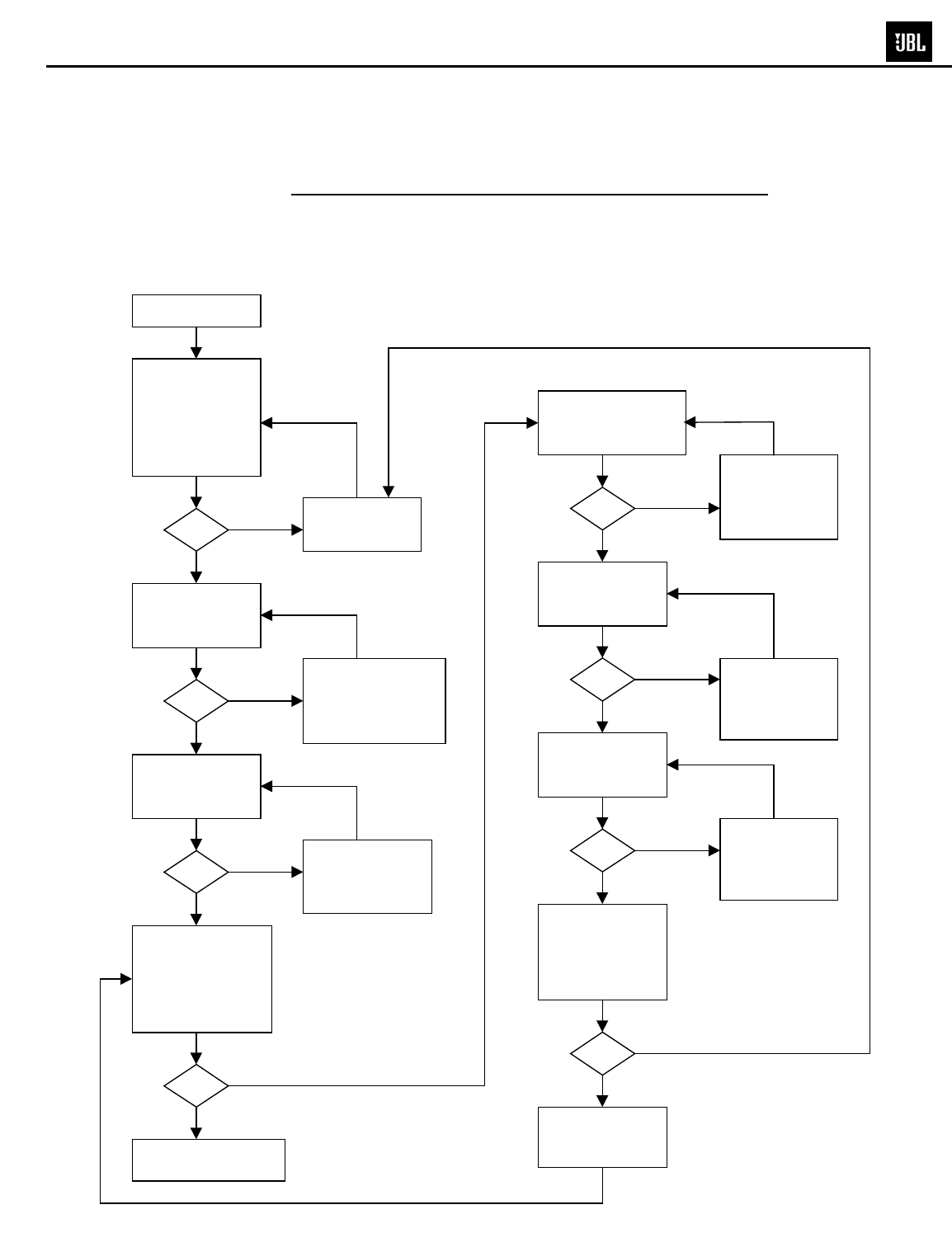
START
Check +/-15V-MOD
+/-15V voltage at
U 6(8),U6(4)
Discharge C37,
Check fuse
transformer, L4,
rectifier, C6 and C8
Use scope to check
switching
frequency U6(7)
100KHz
+/-10% , ~24Vp-p
Check Q4(E)
TO V-
= 0V D.C.
Power up with no
signal input
LED RED
OK
OK
OK
OK
OK
OK
OK
OK
Check
MUTE(+8V) and
Q24,Q25,Q26
Use scope to
check O/P U7(6)
and GND
143Vp-p square
wave shown
Check
L2,L3,C71,C72,
C73
,
C74
I/P:10mv/50HZ
Check +15V/SW
Q4(E) TO V-
15V
Replace
Q18,Q22
CLASS D AMP OK
END
Check
U7,Q16,Q17,
Q20,Q21,R87,
D26,D35,C64
Check
FB1,FB2,C45,
C50,C60,C63,
R81,R82
Check
U7(1) = -58.3V
Check
MUTE(-12.9V),
And
Q24,Q25,Q26
Resistance check
(no load)
between V+ V-,
V+ O/P,V- O/P
and O/P to GND
is > 10K
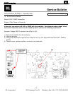
DETAILED TROUBLESHOOTING (CONT'D)
FLOW CHART
19
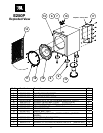
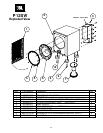
E250P/P12SW subwoofers