


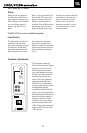
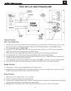
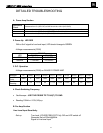
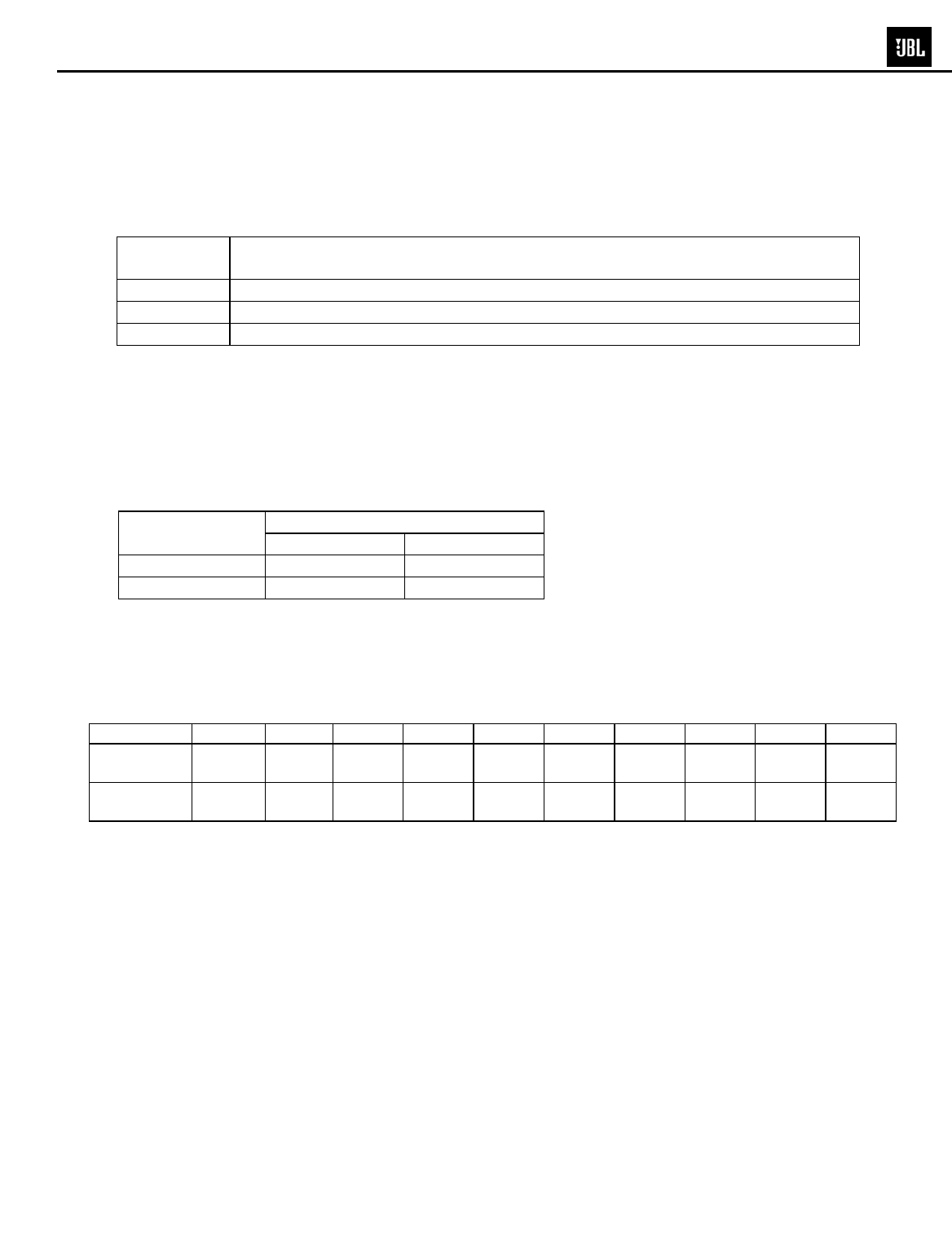
A. Power Amp Section
Resistance
Check
Resistance from S+ (SPK O/P) to GND should be >1M Ω (NO LOAD)
Resistance from V+ (C6 P+) to V- (C8 P-) gradually Fully CHARGED should read >10k Ω
Resistance from V+ (C6 P+) to S+ (SPK O/P) should read >1MΩ
Resistance from V- (C8 P-) to S+ (SPK O/P) should read >1M Ω
2. Power Up LED RED
With a 5mV signal to Low level input, LED should change to GREEN
-Voltage measurements (DVM)
OP AMP
LED
P-U4(1) P-U4(7)
RED 0Vrms 11.84VDC
GREEN 7.13Vrms -12.93VDC
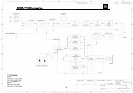
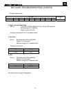
3. D.C. Operation
-Voltage measurements (DVM) on CLASS D POWER AMP
Between V+ Q4(E) Q1(C)
Q10(C)
U7(1) U7(2) U7(4) U7(6) U7(7) U7(8)
And This
Point
GND V- GND GND GND GND GND GND GND GND
Get this
Reading
71.7V 0V -71.7V 0V -71.7V -71.5V -71.2V 0V 0V 4.65V
4. Check Switching Frequency
• Oscilloscope - USE THE PROBE TIP TO U6(7) TO GND
• Reading 100kHz +/-10%,24Vp-p
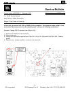
B. Pre Amp Section
Line Level Input Sensitivity
-Set up Turn level, X’OVER FREQ POT Fully CW and LFE switch off
Generator Set at 200mV@50Hz
Signal to Line level input
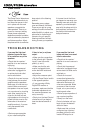
DETAILED TROUBLESHOOTING
17
E250P/P12SW subwoofers