8
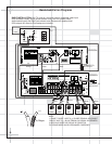
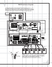
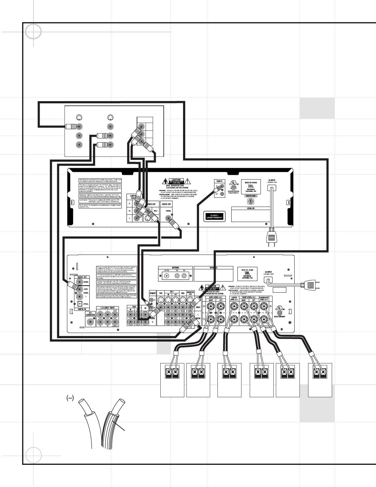
Quick Installation Diagrams
TV
VIDEO IN
AUDIO IN
L
R
AUDIO OUT
L
R
VIDEO OUT
S-VIDEO IN
S-VIDEO OUT
COMPONENT
VIDEO IN
Pr
Pb
Y
White
Red
DCR600
II
DVD600
II
CONNECT TO
AC OUTLET
CONNECT TO
AC OUTLET
Yellow
Black
Orange
(+)
Ridges
– +
SURROUND RIGHT
SPEAKER
– +
SURROUND LEFT
SPEAKER
– +
FRONT RIGHT
SPEAKER
– +
FRONT LEFT
SPEAKER
– +
CENTER
SPEAKER
– +
SUBWOOFER
Yellow
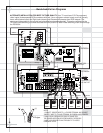
ALTERNATE INSTALLATION FOR BEST PICTURE QUALITY: Your TV must have Y/Pr/Pb component
video inputs (three separate RCA connectors with red-, blue- and green-colored cores), and Left (usually
has a white-colored core) and Right (red-colored core) Stereo audio preamp-level RCA outputs. The
component video cable is not included and should be purchased separately. This setup requires that the
TV’s own video switching is utilized to access the DVD picture. All other video switching is still done through
the DCR600
II
.
NOTES:
1. CONNECT “RIDGED” WIRE TO (+) COLORED TERMINAL AND CONNECT
“SMOOTH” WIRE TO (–) BLACK TERMINAL ON DCR600
II
AND SPEAKERS.
2. WIRE COLOR CODES ARE FOR EASE OF CONNECTION.
THE SPEAKER WIRES CAN BE INTERCHANGED IF NECESSARY.
3. MUST USE VIDEO SWITCHING THROUGH TV TO ACCESS
COMPONENT VIDEO.
Gray
Green
Red White BrownBlue
Composite
Video cable not included


