21
terminal should be connected to the
red (+) terminal on the Side Surround/
Surround Right speaker with the older
color-coding. Connect the black (–) termi-
nals on the CVR700 to the matching black
negative (–) terminals for each side sur-
round speaker
. (See page 42 for more
information on speaker polarity.)
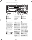
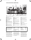
£ Center Speaker Outputs: Connect
these outputs to the matching + and –
terminals on your center channel speaker.
In conformance with the CEA color-code
specification, the green terminal is the
positive (+) terminal that should be con
-
nected to the red (+) terminal on speakers
with the older color-coding. Connect the
black (–) terminal on the CVR700 to the
black negative (–) terminal on the speaker.
(See page 42 for more information.)
¢ Front Speaker Outputs: Connect
these outputs to the matching + or – ter-
minals on your left and right speakers.
When making speaker connections
always make certain to maintain correct
polarity by connecting the color-coding
(white for front left and red for front
right) (+) terminals on the CVR700 to the
red (+) terminals on the speakers and
black (–) terminals on the CVR700 to the
black terminals on the speakers (see
page 42 for more information).
∞ Fan Slots: These ventilation holes
are the output of the CVR700’s airflow
system. To ensure proper operation of the
unit and to avoid possible damage to del
-
icate surfaces, make certain that these
holes are not blocked and that there is at
least three inches of open space between
the vent holes and any wooden or fabric
surface. It is equally important to make
sure that the holes in the top and bottom
covers of the unit are not blocked, either.
It is normal for the fan to remain on at
all times at one of three speeds,
depending on the selection you make in
the
ADVANCED SETTINGS
submenu. By selecting the default
MINIMUM NOISE setting, the fan
will run at its slowest speed at volumes
below –20dB, and at its slightly faster
medium speed at higher volumes. This
setting should only be selected when
the CVR700 is placed on a shelf and
not within an enclosed space. When
the CVR700 is placed inside a cabinet
or other enclosed space, select the
MAXIMUM COOLING setting, in
which the fan will always be on at its
highest setting.
§ Subwoofer Output: Connect this
jack to the line-level input of a powered
subwoofer. If an external subwoofer
amplifier is used, connect this jack to
the subwoofer amplifier input. Use a
Y-adaptor when connecting two sub-
woofers.
¶ DVI/Computer Analog Audio
Inputs:
Connect the left/right analog
audio outputs of a computer or other
device with a DVI output to these jacks
to benefit from the CVR700’s surround
processor for added realism and excite-
ment when playing computer games,
or giving multimedia presentations, or
for other uses. When you have also
connected the computer’s DVI video out-
put to the
DVI/Computer Video Input
, you may also benefit from the
superior visual presentation of the JBL
Cinema V
ision CVPD50 screen.
You may connect any device with left and
right analog audio outputs to these jacks.
• Auxilliary Analog Audio/Video
Inputs:
Connect the left/right analog
audio and composite or S-video jacks of a
video device to these jacks. You may con-
nect any video source such as a VCR,
HDTV receiver, or other device to these
inputs. Note that if the source device
offers digital audio capability, that con-
nection must be made separately, and the
CVR700 configured accordingly. Note that
the Auxiliary Source Input does not have
component video inputs assigned to it
and thus may only be used with compos-
ite or S-video. Therefore, if possible, it
is recommended that an HDTV receiver
be used with the Cable/Sat or even the
Digital Recorder source, so that a compo-
nent video connection may be made. (See
page 46 for more information on configur
-
ing an input for various source options.)
ª Digital Recorder Analog
Audio/Video Inputs:
Connect the
left/right analog audio and composite
or S-video PLA
Y/OUT jacks of a video
recording device such as a VCR, DVD-
Recorder or personal video recorder to
these jacks. The CVR700’s remote control
has a variety of digital recorders avail-
able as the default devices for this input,
but you may connect any video source
such as a VCR, HDTV or cable set-top
box, personal video recorder, or other
device to these inputs. Note that if the
source device offers either digital audio
or component video capability, those con-
nections must be made separately, and
the CVR700 configured accordingly
. (See
page 46 for more information on configur-
ing an input for various source options.)
‚ Digital Recorder Analog Audio/
Video Outputs:
Connect the left/right
analog audio and composite or S-video
RECORD/IN jacks of a video recording
device such as a DVD-Recorder
, personal
video recorder or VCR to these jacks.
⁄ VCR Analog Audio/Video Inputs:
Connect the left/right analog audio and
composite or S-video PLAY/OUT jacks of
a video recording device such as a VCR,
DVD-Recorder or personal video recorder
to these jacks.
¤
VCR
Analog Audio/Video Outputs:
Connect the left/right analog audio and
composite or S-video RECORD/IN jacks of
a video recording device such as a VCR,
DVD-Recorder or personal video recorder
to these jacks.
The CVR700’s remote control has a VCR
as the default device for this input, but
you may connect any video source such
as an HDTV or cable set-top box, personal
video recorder, or other device to these
inputs. Note, however, that the VCR
source is not associated with any digital
audio inputs or component video inputs,
and should therefore only be used as a
last resort for devices that have those
capabilities. The preferred system config-
uration is to connect an HDTV tuner or
digital cable or satellite receiver to the
Cable/Sat source, and to connect a per-
sonal video recorder
, such as a T
iVo,
®
to
the Digital Recorder source.
‹ Cable/Satellite Analog
Audio/Video Inputs:
Connect the
left/right analog audio and composite or
S-video jacks of a video device to these
jacks. The CVR700’s remote control has
a cable, satellite or HDTV set-top as the
default devices available for this input,
but you may connect any video source
such as a VCR, HDTV or satellite receiver
,
personal video recorder, or other device
to these inputs. Note that if the source
device offers either digital audio or com
-
ponent video capability, those connec-
tions must be made separately, and the
CVR700 configured accordingly.
33
34
3
5
36
3
7
38
3
9
40
4
1
42
43
44
45
46
47
48
49
50
51
52
53
54
55
56
57
38
39
4
0
41
3
1
32
30
28
29
2
5
26
27
2
8
29
30
2
4
23
2
2
2
1
20
31
37
36
3
5
34
33
32
31
37
3
6
3
5
34
33
32
48
49
5
0
51
47
4
6
4
5
44
43
42
1 2 3 4 5
6
7
8 9 1
0
1
1
1
2
1
3
1
4
1
5
1
6
1
7
1
8
19 20 21 22 23 24
25 26 27 28 29 30
3
1
3
2
3
3
3
4
3
5
3
6
37 38 39 40 41 42
4
3
4
4
4
5
4
6
4
7
4
8
CVR700 OM 12/17/04 4:23 PM Page 21


