


8
8
Manufactured under license U.S. Patent #’s: 5451, 942; 5,956,674; 5,974,380; 5,978,762; 6,487,535; 7,003,467 & other U.S. and
worldwide patents issued & pending. DTS is a registered trademark & the DTS logos and Symbol are trademarks of DTS, Inc.
© 1996-2007 DTS, Inc. All Rights reserved.
Manufactured under license from Dolby Laboratories. Dolby, Pro
Logic, and the double-D are trademarks of Dolby Laboratories.
Copyright 1992-1999 Dolby Laboratories. All rights reserved.
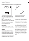
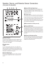
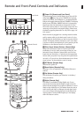
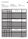
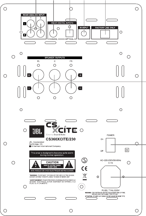
Speaker, Source, and Remote-Sensor Connectors
(rear panel of subwoofer)
0 Speaker Outputs
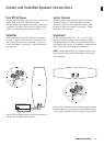
Connect the three speakers here with the speaker wire in
the box, or other suitable wire. There is a Plus (+) and a
Minus (-) wire to each speaker. FL is Front Left speaker, C
is Center, FR is Front Right.
1
Analog Inputs
1 and 2
Connect analog audio outputs from a TV, a DVD or CD
player or any other (line level, not record players) source
with analog left and right RCA phono plug outputs to the
two RCA phono sockets on one of these inputs. An analog
RCA cable is included with the system.
2 Coaxial Digital Input
Connect the coaxial digital output of a DVD or CD player
to this socket. A digital RCA cable is included with the
system.
3
Optical (TOS Link) Digital Input
Connect the optical digital output of any digital source
(MP3 player, portable CD player, stationary DVD or CD
player) to this TOS Link socket. A TOS Link cable must be
purchased separately.
4
Infrared Input
If you prefer to place the subwoofer somewhere discreet,
the infrared sensor on its front panel may not be able to
receive commands from your remote control. In this case,
use the extra infrared receiver placed underneath the
center speaker instead. The separate sensor has a 3,5mm
stereo mini-jack, which plugs into this socket. Both sen-
sors are active simultaneously.
5
Data connection for factory use only
6 Power On/Off Switch
When in OFF position, this switch disconnects the system
completely from AC power. This means that there is no
stand-by power consumption, and the system cannot be
switched on with the remote control. It is recommended
to set this switch to OFF when not using the system for a
prolonged period of time. Switch to ON to permit normal
operation.
7
AC Power Cord Socket and Fuse
Insert the proper end of the power cord here, the other
end into a wall socket. If the internal fuse should blow,
pry open the small drawer beneath the AC plug with a
screwdriver to slide out the fuse.