


7
7
WWW.JBL.COM
English
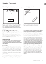
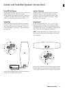
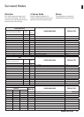
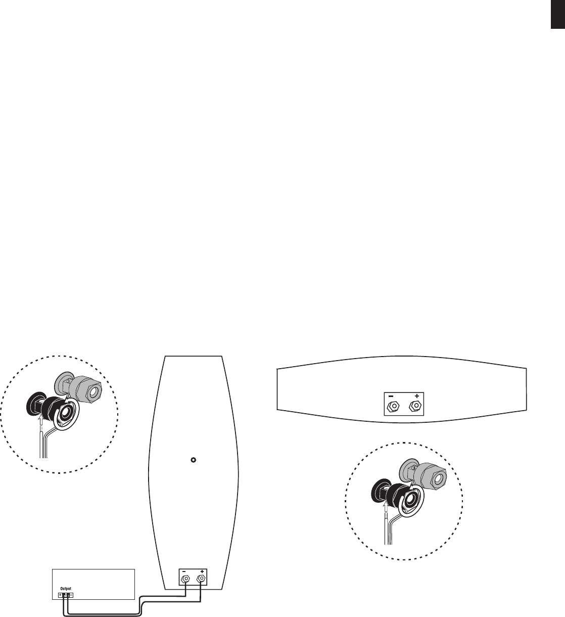
Figure 4. Wiring diagram shows polarity connections for
one channel of a home theater system.
Figure 5. The satellites and center channel speaker feature
terminals that can be connected in several different ways
– e.g., spade terminals and direct wiring (as shown here).
Center and Satellite Speaker Connections
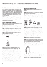
Turn Off All Power
After placing the speakers, you are ready to connect your
system. First, turn off all audio-system power.
Use the speaker wire included (or similar) to make your
connections. The side of the wire with a ridge or other
coding is usually considered positive polarity (i.e., +).
Satellites
Observe polarities when making speaker connections,
as shown in Figure 4. Connect each + terminal on the
back of the subwoofer to the respective + (red) termi-
nal on each speaker. Connect the – (black) terminals in
the same way.
Center Channel
Observe polarities when making speaker connections,
as shown in Figure 5. Connect the center channel +
terminal on the back of the subwoofer to the + (red)
terminal on the center speaker. Connect the – (black)
terminals in the same way.
Important!
Do not reverse polarities (i.e., + to –, or – to +) when
making connections. Doing so will cause poor imaging
and diminished bass response. Be certain that positive
and negative wire strands are completely isolated to avoid
short circuits that may damage your equipment.
NOTE: A small socket wrench is provided to help in prop-
erly tightening the terminals. Hand-tighten only and do
not overtighten.
Red = +
Black = –
Red = +
Black = –
No Stripe = –
Speaker Wire
One Channel Shown
Subwoofer Speaker Outputs
(rear view)
Stripe = +
0
Loosen
Terminal
1
Insert Bare
End; Tighten
Terminal
Red = +
Black = –
No Stripe = –
Speaker Wire
Stripe = +
0
Loosen
Terminal
1
Insert Bare
End; Tighten
Terminal