10
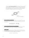
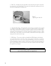
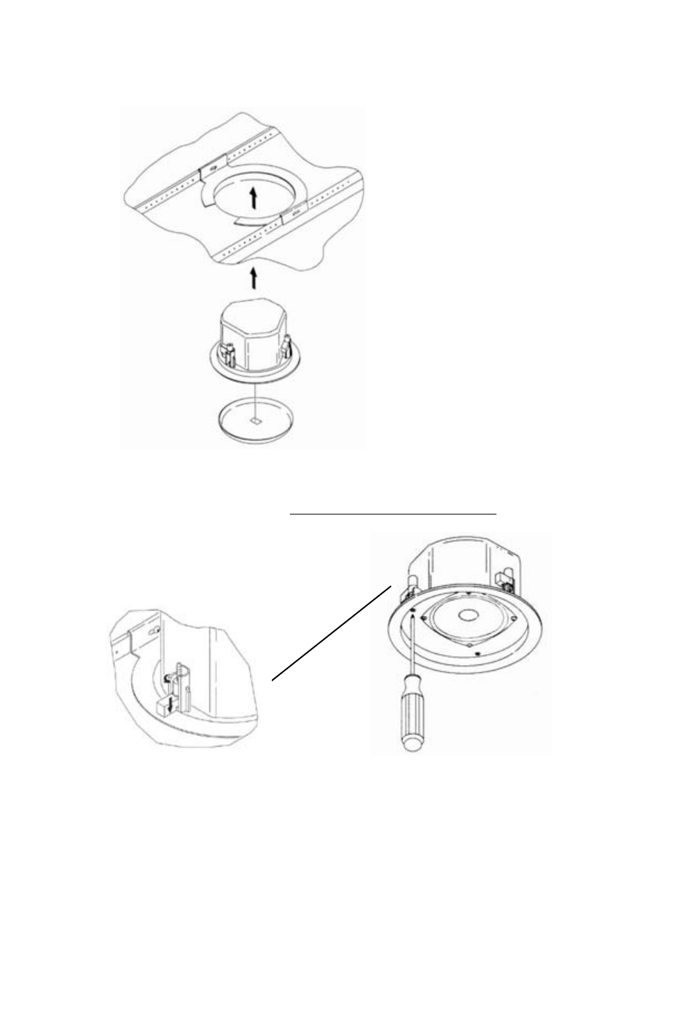
Then tighten the mounting tabs by turning the screw CLOCKWISE until tight. The first ¼
clockwise turn rotates the attachment tabs outward and the remaining turns tighten the tabs
down onto the back of the ceiling surface. DO NO
T OVERTIGHTEN.
Figure 9:
Tightening Mounting Tabs
Step 6 - Connect a Secondary Support Line to Seismic Tab - A tab is provided on the side
of the Control 24C/CT Micro and the Control 24CT MicroPlus for connection to an inde-
pendent secondary support point. Some construction codes require using this secondary sup-
port point, by connecting a support line to a separate secure support point.
Consult construction codes in your region.
Step 7 - Insert the Grille - Consider which direction the logo is facing and press the grille into
place until the front of the grille is flush with the rim. Make sure grille is securely seated to pre-
vent it from vibrating loose and falling.
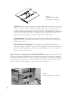
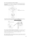
Figure 8:
Inserting Speaker Into Ceiling
Step 5 - Insert the Speaker Into the Ceiling and Tighten.
Insert the speaker into the ceiling as far as it goes, until the front baffle rim touches the ceiling.
Turn the attachment screws to tighten the mounting tabs, by using the following directions:
IMPORTANT - For each attachment screw, FIRST turn ½ turn COUNTER-CLOCKWISE
to release the mounting tab from its guide.


