


10
Front & Rear Panels—Continued
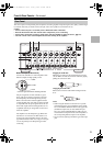
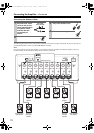
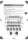
INPUT SELECT switch
This switch is located between the balanced input
and single-ended RCA input for each channel. Use
this switch to select the input type for its channel.
When setting the switch to the upper side, the bal-
anced input is selected.
When setting the switch to the lower side, the RCA
audio input is selected.
Notes:
• Do not change the INPUT SELECT switch setting
when the amplifier is turned on.
• Make sure that connections have been made only to
the inputs selected with the INPUT SELECT switches
and nothing is connected to the other ones.
Unbalanced Input (single end RCA input)
Connect AV controllers or control amplifiers with
single-ended outputs.
Notes:
• When using this single-ended connection for a spe-
cific channel, set the INPUT SELECT switch to the
lower side (the RCA audio input side), use commer-
cial RCA audio pin cable and connect the single-
ended outputs.
• Do not connect anything to the balanced input jack.
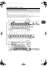
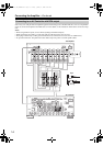
OUTPUT (Speaker output and binding post)
These terminal posts are for connecting the front
L/R, center, surround L/R, surround back L/R, and
front high/wide L/R speakers.
The FRONT L/R and SURR BACK L/R terminal
posts can be used with front speakers and surround
back speakers respectively, or used to bi-amp the
front speakers. See “Bi-amping the Front Speakers”
on page 15.
SPEAKER IMPEDANCE switch
Use this switch to select the speaker impedance.
4Ω: Select if the impedance of any speaker is
4 ohms or more but less than 6.
6Ω: Select if the impedances of all speakers are
between 6 and 16 ohms.
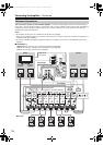
AUTO POWER DOWN switch
You can use the auto power-down function. If the
amplifier receives no signal for 3 hours, it will auto-
matically enter standby mode. Once the auto power-
down function has been activated, the amplifier will
not automatically turn on even if it receives the sig-
nal. To turn on the amplifier, press the On/Standby
button manually. You can also disable the function
by setting this switch to OFF side.
Default setting: ON (Australian models), OFF
(North American models)
Notes:
• Regardless of the position of this switch, this function
will not work when the amplifier has been turned on
by the 12V trigger.
• Before entering standby mode by the auto power-
down function, the amplifier notifies you by flashing
the On indicator for 10 seconds.
• Depending on some sources, the auto power-down
function may activate during playback.
12V TRIGGER IN
Connects to the 12V trigger output terminal on the
other component to control the amplifier. This
enables the amplifier to turn on or go into standby
state based on the power on/standby status of the
connected component.
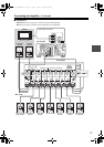
Use the supplied or commercially available 1/8-inch
mono cable to connect to the 12V trigger output ter-
minal on the other device.
The tip polarity of the connectors are as shown
below.
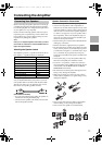
AC INLET
Plug the supplied power cord into this AC INLET
and then into the power outlet on the wall.
• Do not plug the amplifier into the AC outlet other than
an AC wall socket.
• Do not use a power cord other than the one supplied
with the amplifier. The power cord supplied is
designed for use with the amplifier and should not be
used with any other device.
• Never have the power cord disconnected from the
amplifier while the other end is plugged into the wall
outlet. Doing so may cause an electric shock. Always
connect by plugging into the wall outlet last and dis-
connect by unplugging from the wall outlet first.
• Before you plug in the amplifier, confirm that all con-
nections have been made properly.
• Turning on the power may cause a momentary power
surge, which might interfere with other electrical
equipment on the same circuit, such as computers. If
this happens, use a wall outlet on a different circuit.
RCA type
5 to 12 volts, positive
tip polarity
To an AC wall
outlet
Power cord
(supplied)
DTA-70.1_En_100108.book Page 10 Friday, January 8, 2010 2:04 PM