


2
Insignia NS-R2000 Stereo Receiver
www.insignia-products.com
• Do not block any ventilation openings. Install
in accordance with these instructions. Slots
and openings in the cabinet are provided for
ventilation, to ensure reliable operation of
your receiver, and to protect it from
over-heating. The openings should never be
blocked by placing your receiver on a bed,
sofa, rug or other similar surface. This
receiver should not be placed in a built-in
installation such as a bookcase or rack
unless correct ventilation is provided or these
instructions have been adhered to.
• Do not install near any heat sources such as
radiators, heat registers, stoves, or other
electronic devices (including amplifiers) that
produce heat.
• Do not defeat the safety purpose of the
polarized or grounding-type plug. A polarized
plug has two blades with one wider than the
other. A grounding type plug has two blades
and a third grounding prong. The wide blade
or the third prong are provided for your safety.
If the provided plug does not fit into your
outlet, consult an electrician for replacement
of the obsolete outlet.
• Protect the power cord from being walked on
or pinched particularly at plugs, receptacles,
and the point where they exit from your
receiver.
• Use only attachments or accessories
specified by Insignia.
• Use only with the cart,
stand, tripod, bracket, or
table specified by
Insignia, or sold with this
receiver. When a cart is
used, use caution when
moving the cart/receiver
combination to avoid
injury from tip-over.
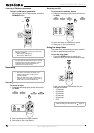
• If an outside antenna or cable system is
connected to your receiver, make sure that
the antenna or cable system is grounded to
provide some protection against voltage
surges and built-up static charges. Article
810 of the National Electrical Code,
ANSI/NFPA 70, provides information with
regard to proper grounding of the mast and
supporting structure, grounding of the lead-in
wire to an antenna discharge unit, size of
grounding conductors, location of
antenna-discharge unit, connection to
grounding electrodes, and requirements for
the grounding electrode.
• Use No. 10AWG (5.3 mm
2
) copper,
No. 8AWG (8.4 mm
2
) aluminum,
No. 17AWG (1.0 mm
2
) copper-clad steel
or bronze wire, or larger, as a ground wire.
• Secure the antenna lead-in and ground
wires to the house with stand-off
insulators spaced from 4-6 feet
(1.22-1.83 meter) apart.
• Mount the antenna discharge unit as
close as possible to where the lead-in
enters the house.
• Use a jumper wire not smaller than
No. 6AWG (13.3 mm
2
) copper, or the
equivalent, when a separate
antenna-grounding electrode is used. See
ANSI/NFPA70.
• Unplug this receiver during lightning storms
or when unused for long periods of time.
• Refer all servicing to qualified service
personnel. Servicing is required when your
receiver has been damaged in any way, such
as power-supply cord or plug is damaged,
liquid has been spilled or objects have fallen
into your receiver, your receiver has been
exposed to rain or moisture, does not operate
normally, or has been dropped.
• When replacement parts are required, be
sure the service technician uses replacement
parts specified by the manufacturer or have
the same characteristics as the original part.
Unauthorized substitutions may result in fire,
electric shock, or other hazards.
• Upon completion of any service or repairs to
this receiver, ask the service technician to
perform safety checks to determine that your
receiver is in proper operation condition.
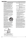
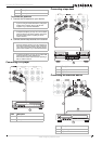
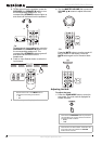
Reference Grounding component
1 Electric service equipment
6
7
5
2
1
3
4
2 Power service grounding
electrode system
(NEC Art 250, Part H)
3 Ground clamp
4 Grounding conductors (NEC
Section 810-21)
5 Antenna discharge unit (NEC
Section 810-20)
6 Ground clamp
7 Antenna lead-in wire
Reference Grounding component