


2
4
INSTALLATION AND CONNECTIONS
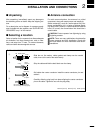
n Unpacking
After unpacking, immediately report any damage to
the delivering carrier or dealer. Keep the shipping car-
tons.
For a description and a diagram of accessory equip-
ment included with the repeater, see ‘SUPPLIED AC-
CESSORIES’ on p. ii of this manual.
n Selecting a location
Select a location for the repeater that allows adequate
air circulation, free from extreme heat, cold, or vibra-
tions, and away from TV sets, TV antenna elements,
radios and other electromagnetic sources.
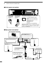
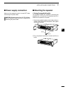
n Antenna connection
For radio communications, the antenna is a critical
component, along with output power and sensitivity.
Select antenna(s), such as a well-matched 50 ˘ an-
tenna, and feedline. 1.5:1 or better of Voltage Stand-
ing Wave Ratio (VSWR) is recommended for desired
band. Of course, the transmission line should be a
coaxial cable.
CAUTION: Protect repeater from lightning by using
a lightning arrestor.
NOTE: There are many publications that describe
proper antennas and their installation. Check with
your local dealer for more information and recom-
mendations.
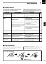
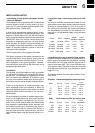
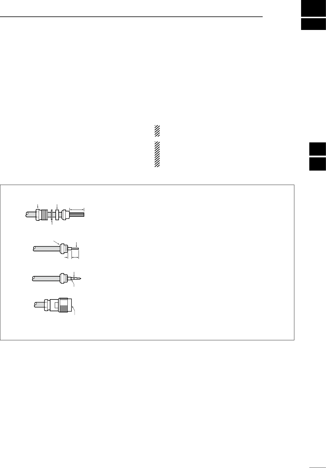
TYPE-N CONNECTOR INSTALLATION EXAMPLE
15 mm (
19
⁄32 in) 6 mm (
1
⁄4 in) 3 mm (
1
⁄8 in)
Slide the nut, flat washer, rubber gasket and clamp over the coaxial
cable, then cut the end of the cable evenly.
Strip the cable and fold the braid back over the clamp.
Soft solder the center conductor. Install the center conductor pin and
solder it.
Carefully slide the plug body into place aligning the center conductor
pin on the cable. Tighten the nut onto the plug body.
q
w
e
r
15 mm
3 mm
6 mm
No space
Solder hole
Be sure the center conductor is
the same height as the plug body.
Clamp
Center
conductor
Washer
Nut Rubber gasket
1
2
3
4
5
6
7
8
9
10
11
12
13
14
15
16
17
18
19
20
21