


11
6
ABOUT CE
• Typical installation example
A UHF base station transmitter is to be installed on
the roof of an office.
The transmit power is 25 watts, there is 20 m of
RG-213 coaxial cable and the antenna is vertically
polarised dipole.
The specification of the RG-213 cable gives a loss
of 1.5 dB/10 m. There will be 3 dB loss for the 20 m
length used.
The RF power at the antenna input will be 12.5 watts.
The dipole antenna has a forward gain of 0 dBd or
1.6, giving an EIRP of 20 watts.
Referring to the table above for VHF/UHF vertical
antennas, this gives a front clearance distance of ap-
prox. 1.5 m and a height clearance of 3 m.
The antenna installation needs to ensure that the low-
est part of the antenna is at least 3 m above any point
where the general public may gain access and that
they cannot pass within 1.5 m in front of the antenna.
If there is no general public access to the roof in
question then the antenna could be mounted on a
short stub mast. If there is such access to the roof
then the antenna could be mounted on top of a short
mast of 3.2 m high. The mast position should be such
that the antenna can radiate clearly i.e. no other ob-
ject or structure is within 1.5 m (preferably more).
It should be relatively easy to fulfil all these recom-
mendations.
If for any reason such minimum distances are impos-
sible to guarantee then some type of access con-
trol fence or barrier around the antenna installation
should be provided.
Should a Yagi type antenna be used then you will
have to obtain a 3 dimensional polar plot of the radia-
tion characteristic from the manufacturer and evaluate
the clearance distances in both vertical and horizontal
planes.
• Operating Notes
All of the above comments on RF safety assume that
the radio is transmitting continuously in a constant
carrier mode such as FM or RTTY etc.
The RF exposure limits recommended by the EC are
based on the mean power averaged over a 6 minute
period.
Therefore if the total transmit time during any 6
minute period is reduced, then the installation will be
even further within the recommended limits.
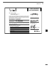
CE Versions of the IC-FR6100 which dis-
play the “CE” symbol on the serial number
seal, comply with the essential require-
ments of the European Radio and Tele-
commun ication Termi nal Direc tive
1999/5/EC.
This warning symbol indicates that this
equipment operates in non-harmonised
frequency bands and/or may be subject to
licensing conditions in the country of use.
Be sure to check that you have the correct
version of this radio or the correct pro-
gramming of this radio, to comply with na-
tional licensing requirement.
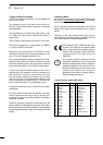
• List of Country codes (ISO 3166-1)
1 Austria AT
2 Belgium BE
3 Bulgaria BG
4 Croatia HR
5 Czech Republic CZ
6 Cyprus CY
7 Denmark DK
8 Estonia EE
9 Finland FI
10 France FR
11 Germany DE
12 Greece GR
13 Hungary HU
14 Iceland IS
15 Ireland IE
16 Italy IT
17 Latvia LV
18 Liechtenstein LI
19 Lithuania LT
20 Luxembourg LU
21 Malta MT
22 Netherlands NL
23 Norway NO
24 Poland PL
25 Portugal PT
26 Romania RO
27 Slovakia SK
28 Slovenia SI
29 Spain ES
30 Sweden SE
31 Switzerland CH
32 Turkey TR
33 United Kingdom GB
Country Codes Country Codes