


3
1
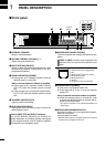
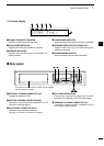
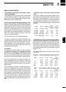
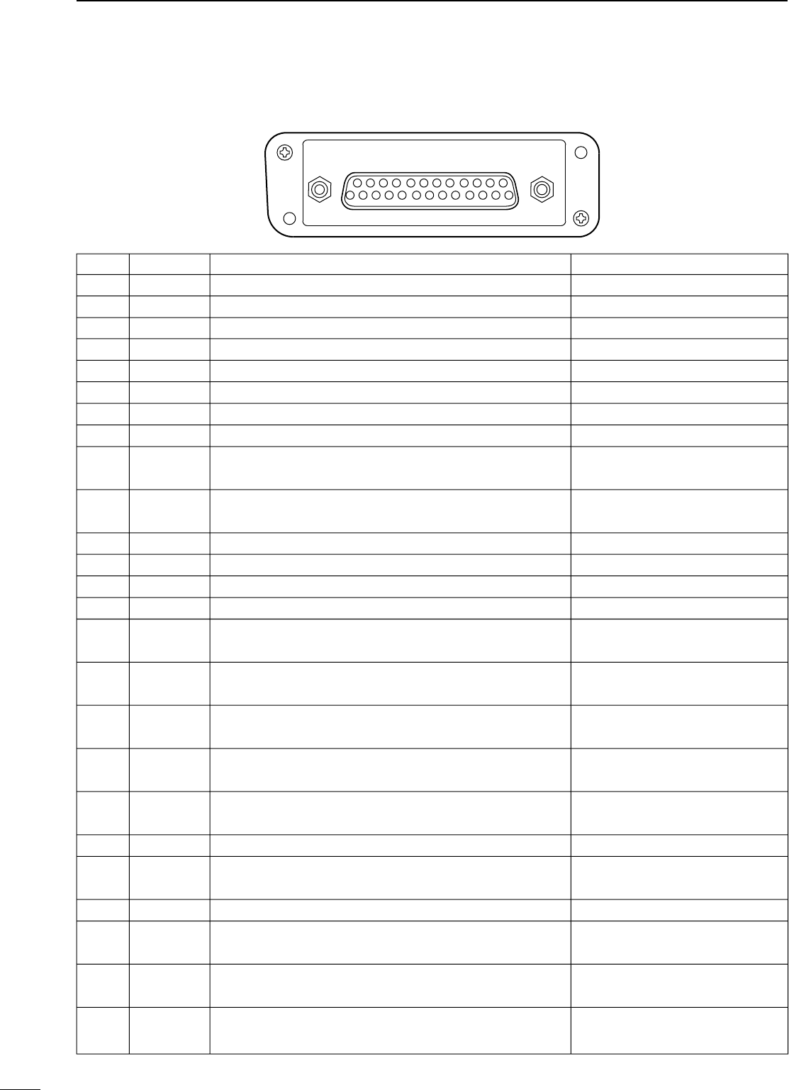
PANEL DESCRIPTION
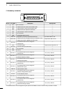
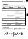
D Accessory connector
q !3
!4 @5
Specification
Description
Pin NamePin No.
NC
TXD
RXD
RTS
CTS
NC
GND
MOD IN
DISC OUT
EXT. D/A
VCC
EXT. A/D
NC
GND
EXT.I/O 15
EXT.I/O 16
EXT.I/O 17
EXT.I/O 18
EXT.I/O 19
DATA IN
EXT.I/O 21
AF OUT
EXT.I/O 23
EXT.I/O 24
EXT.I/O 25
1
2
3
4
5
6
7
8
9
10
11
12
13
14
15
16
17
18
19
20
21
22
23
24
25
No connection
Output terminal for serial communication data.
Input terminal for serial communication data.
Output terminal for request-to-send data.
Input terminal for clear-to-send data.
No connection
Serial/digital signal ground
Modulator input from an external terminal unit.
Output terminal for AF signals from the AF detector circuit.
Output level is fixed, regardless of [AF] control.
The desired function can be assigned.*
(Default: Null)
13.2 V DC output
Customize A/D input (Not used)
No connection
Ground
The desired function can be assigned.*
(Default: Null)
The desired function can be assigned.*
(Default: P0 Monitor Output)
The desired function can be assigned.*
(Default: Busy Output)
The desired function can be assigned.*
(Default: Null)
The desired function can be assigned.*
(Default: EPTT Input)
Input terminal for data.
The desired function can be assigned.*
(Default: Analog Audible Output)
The AF detector Output.
The desired function can be assigned.*
(Default: Mic Mute Output)
The desired function can be assigned.*
(Default: Null)
The desired function can be assigned.*
(Default: Mic Hanger Output)
—
—
—
—
—
—
—
Input level: 300 mV rms
Output level: 300 mV rms
—
Output current: Less than 1 A
—
—
—
+5 V pull up, Active=L
+5 V pull up, Active=L
+5 V pull up, Active=L
+5 V pull up, Active=L
+5 V pull up, Active=L
—
+5 V pull up, Active=L
—
+5 V pull up, Active=L
+5 V pull up, Active=L
+5 V pull up, Active=L
* The desired function can be assigned using the optional CS-FR5000 cloning software. Ask your dealer for details.