


7800 SERIES RM7824A RELAY MODULE
65-0155—1
3
Weight:
RM7824A with Dust Cover: 1 pound, 12 ounces, unpacked.
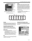
IMPORTANT
Flame Detection System available for use with
RM7824A. To select your Plug-in Flame Signal
Amplifier and applicable Flame Detector, see Table 2
and Fig. 3.
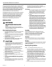
CAUTION
To prevent the control from sequencing on power up,
RM7824 Relay Modules with software revision 2424
or less should not be used with R7848 Infrared
Amplifiers and C7015 Infrared Flame Detectors,
unless a ten-second delay is provided.
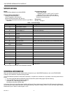
Table 2. Flame Detection Systems.
Plug-in Flame Signal Amplifiers Applicable Flame Detectors
Type Color Self-Checking Model
Flame Failure
Response Time Fuel Type Models
Rectification Green Dynamic
Self-Check
R7824C
a
3 sec Gas, oil, coal Ultraviolet
(Purple Peeper)
C7024E,F
Infrared Red No R7848A 3 sec Gas, oil, coal Infrared
(Lead Sulfide)
C7015.
Dynamic
AMPLI-CHECK®
R7848B 3 sec Gas, oil, coal Infrared
(Lead Sulfide)
C7015.
a
Circuitry tests all electronic components in the flame detection system (amplifier and detector) 12 times a minute during burner
operation and shuts down the burner if the detection system fails.
Table 3. Sequence Timing For Normal Operation.
Device Initiate Standby Pilot Flame Establishing Period Run
RM7824A 10 sec * 4 or 10 sec *
*STANDBY and RUN can be an infinite time period.
Approval Bodies:
Underwriters Laboratories Inc. Component Recognized:
File no. MP268, guide no. MCCZ.
Canadian Standards Association certified: LR9S329-3.
Federal Communications Commission: Part 15,
Class B-Emissions.
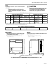
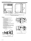
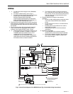
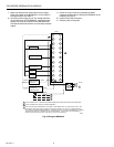
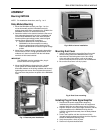
Mounting:
Q7800A for panel mount or Q7800B for wall or burner mount.
Required Components:
Plug-in Flame Signal Amplifier; see Fig. 2.
Q7800A or Q7800B.
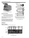
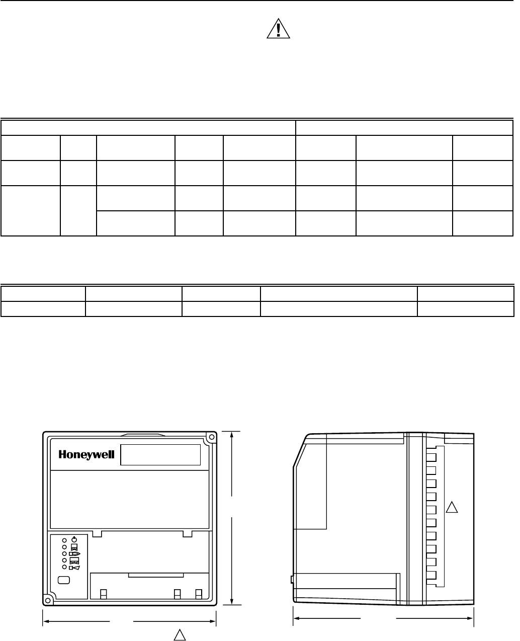
5
(127)
5 (127)
M5872
BURNER CONTROL
REMOVE ONLY FOR TERMINAL TEST ACCESS.
1
1
5-1/4 (133)
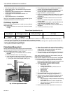
Fig. 1. Mounting dimensions of RM7824A Relay Module and Q7800A Subbase in in. (mm).