7800 SERIES RM7824A RELAY MODULE
65-0155—1
19
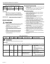
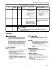
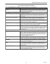
Table 7. Sequence And Status Hold Information.
NOTE: Normal sequences are in bold type, while abnormal sequences are in standard type.
Sequence Information
INITIATE The LED indicates the burner status, POWER, which is a stabilization period for
the RM7824A to check for any fluctuations in dc voltage inputs or control input on
power-up or during normal operation.
If the RM7824A is in a HOLD status, the following conditions could exist:
INITIATE HOLD (Vdc Frequency/noise) The LED indicates the burner status, POWER, and that the RM7824A is waiting
for excess line noise to clear up. The burner sequence will not advance into
STANDBY until the excess line noise, which prevents sufficient read of the voltage
inputs, ceases.
INITIATE HOLD (AC Line Dropout) The led indicates the burner status, POWER, and that DC Bus power has
momentarily dropped out. The burner sequence will not advance into STANDBY
until the DC Bus voltage has stabilized throughout the INITIATE sequence.
INITIATE HOLD (AC Frequency) The LED indicates the burner status, POWER, and that the internal timing
functions are out of synchronization. The burner sequence will not advance into
STANDBY until the internal timing is synchronized.
INITIATE HOLD (Low Line Voltage) The LED indicates the burner status, POWER, and that low DC Bus voltage has
occurred. The burner sequence will not advance into STANDBY until the DC Bus
voltage is at a sufficient level for proper operating parameters.
STANDBY The LED indicates the burner status, POWER. The burner can be placed in
STANDBY by opening the burner switch or if the operating controller indicates its
setpoint has been satisfied. If a demand is present for burner operation, the burner
sequence will not advance from STANDBY to SAFE START CHECK until the
recycle limits close.
If the RM7824A is in a HOLD status, the following conditions could exist:
STANDBY HOLD: F/G (Flame Detected) The LEDs indicate the burner status, POWER and FLAME, and that a flame is
detected. A demand is present for burner operation. The burner sequence will not
advance to SAFE START CHECK because a flame is detected as being present.
The sequence will not advance to SAFE START CHECK until the flame signal
clears. If the flame signal does not clear within
40 seconds, the RM7824A will lockout.
SAFE START CHECK The LED indicates the burner status, POWER, which is the period of time after
STANDBY. The RM7824A is verifying that a flame is not present before the start
of Ignition Trials. If a flame is present, the RM7824A will recycle to STANDBY.
PILOT IGN The LEDs indicate the burner status, POWER, PILOT and FLAME, which is the
period of time the RM7824A permits the pilot valve and ignition to be energized
and the pilot flame to be established.
RUN The LEDs indicate the burner status, POWER, PILOT, FLAME and MAIN, which is
the period of time after the Ignition Trials and before the operating controller
setpoint is reached. During this time, the burner is firing under the control of the
operating controller.
RESET/ALARM TEST The LED indicates the burner status, POWER and ALARM. This condition
indicates that the reset pushbutton is pressed. If it is held for more than four
seconds, the alarm output is energized. The alarm output will be de-energized
after the reset pushbutton is released.


