


11
COMPONENT NAMES
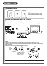
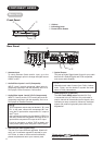
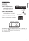
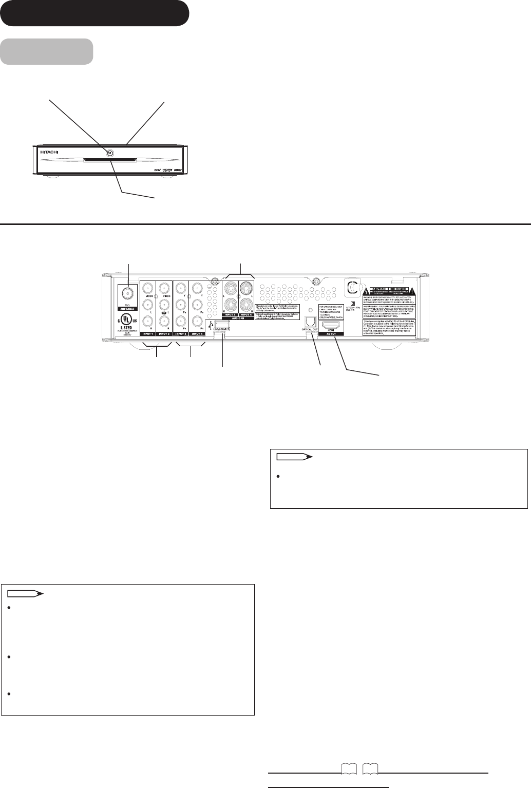
Main Unit
Front Panel
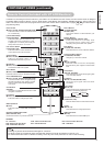
Rear Panel
q
Cabinet
w
Indicating Lamp
e
Power Off/On button
*Please refer to
14
~
15
for detailed information
regarding the connections.
q
w
e
t
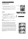
q
Antenna Input
To switch between Cable and Air input, go to the
Channel Manager option to change the signal source
CABLE or AIR.
w
Audio/Video inputs 1 and 2 (Composite)
INPUT-1 and 2 provide composite Video jacks for
connecting equipment with this capability, such as a
DVD player, Game Console or Camcorders.
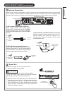
e
Audio/Video inputs 3 and 4 (Y-P
B
P
R
Components)
INPUTS 3 and 4 provide Y-P
B
P
R
and Audio jacks for
connecting equipment with this capability, such as a
DVD player or Satellite Receiver.
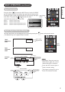
r
USB Port(For S/W Upgrade only)
This slot is for future software upgrades. Hitachi will
notify you if a software upgrade is required for your
A/V Center. In order to receive written notication,
please complete and return your warranty card.
t
Optical Output
This jack provides Digital Audio Output for your audio
device that is Dolby® Digital and PCM compatible,
such as an audio amplier.
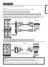
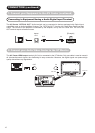
y
HDMI Output(To UT Monitor)
The A/V Center HDMI output terminal (AV Out)
is connected to the UT Monitor. Only one cable is
used to transmit all video/audio/control signals, thus
facilitating an easy connection. Moreover, the digital
signals can produce high quality data without any
degradation.
w
q
e
e
r
y
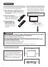
NOTE
Your component outputs may be labeled Y, B-Y, and
R-Y. In this case, connect the components B-Y out-
put to the P
B
input and the components R-Y output to
the P
R
input.
Your component outputs may be labeled Y-CBCR. In
this case, connect the component CB output to the P
B
input and the component CR output to the P
R
input.
It may be necessary to adjust TINT to obtain opti-
mum picture quality when using the Y-PBPR inputs .
NOTE
*Manufactured under license from Dolby Labora-
tories. “Dolby” and the double-D symbol are trade-
marks of Dolby Laboratories.