


12
2 Description
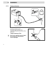
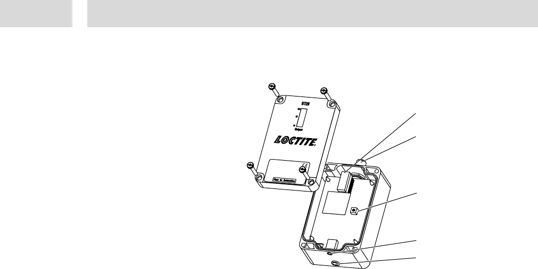
2.2 Displays, Operating Elements and Connections
1
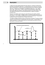
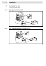
LED Row 1-10 V OUTPUT
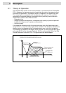
Displays the measured and amplified signal from the sensor during a measuring. The
best adjustment of the amplification is during a measuring (dispensing) the signal will be
not higher than 5 V. It has to be adjusted at the potentiometer 3.
At the beginning of a measuring cycle the signal increases more than the adjusted 5 V.
It shows you that the pressure sensor works well. If the sensor is damaged, no signal will
be displayed.
2
4 pin Plug for connection to controller
The supplied connection cord is connected here (Pin assignments see Section 8.2).
3
Potentiometer R10 to adjust the amplification factor
It is necessary to adjust the amplification factor for getting an optimum signal for the
interpretation at the Loctite controller.
4
Service Socket, for Loctite service only
5
4 pin Socket for connection the pressure sensor
The cable of the pressure sensor is connected here (Pin assignments see Section 8.2).
1
2
3
4
5
Loctite (Ireland) Ltd.
Made in Germany
cat. no. 97211
Tallaght Business Park
Whitestown
Tallaght, Dublin 24, Ireland