


14 INSTALLATION AND CONNECTIONS
Installation and Connections
• If your video display has component video
inputs (Y/Pr/Pb), connect the Component
Video Outputs
K
.
• If your display does not have digital or
component video inputs, connect the Video
Monitor Output
B
on the AVR to the
matching input on your display. Only one
connection is needed, and S-video is the higher
quality signal.
HDMI Connections
HDMI
™
is the abbreviation for High-Definition
Multimedia Interface, which is quickly becoming
the standard connection point between
advanced video/audio source products and
displays, particularly for high-definition video
signals. HDMI is a digital connection, eliminating
the need to convert signals back and forth from
digital to analog.
Some source or display components in your
system may use DVI (Digital Video Interface) for
digital video connections. DVI carries the same
digital video signals as HDMI but uses a larger
connector and does not transport audio or
control signals. In most cases, you may mix and
match DVI and HDMI digital video connections
by using optional connector adapters. Note,
however, that some DVI-equipped video displays
are not compatible with the HDCP copy
protection coding that is increasingly carried with
signals connected via HDMI. If you have an
HDMI source and a DVI-equipped display, you
may occasionally be unable to view a program if
the display does not include HDCP. This is not the
fault of the AVR or your source; it simply
indicates that the video display is not
compatible.
The AVR 155 is equipped for HDMI switching,
which means that it is able to select either of the
three HDMI inputs as the source that feeds your
system’s video display. This preserves the digital
signal in its original form by passing it directly
through from source to display. However, this
also means that the AVR does not have access to
the signal and thus it is not able to add menus or
on-screen messages to HDMI signals, or to
process the audio that may be part of the signal
in an HDMI connection.
Therefore, the following connections are required
when the AVR 155 is used with HDMI sources:
• Connect the HDMI output of a source to either
of the HDMI Inputs
V
.
• Connect the HDMI Output
W
of the AVR to
an HDMI input on your display.
• Connect either an optical or coaxial digital
audio output from the source to the AVR. The
default connections are Coaxial 2
N
for a
source connected to HDMI 1
V
and
Optical 2
R
for a source connected to
HDMI 2
V
. You may use any digital or analog
audio source in conjunction with the HDMI
inputs, but if it varies from the default you
must make a change to the input’s setting, as
shown on page 18.
• Even when HDMI inputs are used, it is impor-
tant to make sure that a component, S-video
or composite video connection is made
between the AVR and your display. This is
needed to view both the setup menus and on-
screen messages, and to view other (non-
HDMI) video sources. The AVR 155 does not
convert analog video signals to HDMI.
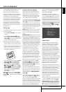
• All component inputs/outputs can be used for
RGB signals too, in the same way as described
for the Y/Pr/Pb signals, then connected to the
jacks with the corresponding color.
But this is only correct as long as only the
three RGB video signals are output by the
video source, with a sync signal in the "G"
signal only, without any sync signal output
separately by the source.
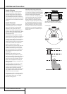
SCART A/V Connections
For the connections described above your video
device needs RCA (cinch) connectors or/and S-
Video connectors for all Audio and Video signals:
Any normal video device (Not SVHS or High 8)
for only playback needs 3 RCA jacks, VCRs for
record and playback even 6 RCA jacks. Any
S-Video device (SVHS, High 8) needs 2 RCA
(Audio) and 1 S-Video jack (Video), if it´s a play-
back unit, or 4 RCA (Audio In/Out) and 2 S-Video
(Video In/Out) jacks, if it´s a recording VCR.
Many european video devices are equipped with
RCA (Cinch) or S-Video jacks only partially, not
for all audio and video in/outputs needed as
described above, but with a so called Scart or
Euro-AV connector (almost rectangular jack with
21 pins, see drawings on next page).
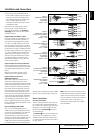
In that case the following Scart to Cinch
adapters or cables are needed:
• Units for playback, such as satellite receivers,
camcorders, DVD or LD players, need an
adapter from Scart to 3 RCA plugs, see fig. 1
(normal video devices) or from Scart to 2
RCA+1 S-Video plugs, see fig. 4 (S-Video
devices).
• HiFi VCRs need an adapter from Scart to 6 RCA
plugs, see fig. 2 (normal video), or from Scart
to 4 Audio+2S-Video jacks, see fig. 5
(S-Video VCR). Read carefully the instruction
attached to the adapter to find which of the six
plugs is used for the record signal to the VCR
(connect with the AVR´s Out jacks) and for the
playback signal from the VCR (connect with
the AVR´s In jacks). Do not misconnect Audio
and Video signals. Don´t hesitate to consult
your dealer, if you are uncertain.
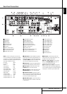
4. Connect the digital audio outputs of a CD,
MD or DVD player, satellite receiver, cable box or
HDTV converter to the appropriate Optical or
Coaxial Digital Inputs
RN*Ó
.
Remember that the DVD source defaults to the
Coaxial 1 Digital Input
N
. All other sources
default to their analog inputs, although any
source may be assigned to any digital audio
input on the receiver.
NOTE: When connecting a device such as a
digital cable box or other set-top tuner product
with a digital audio output, we recommend that
you connect both the digital and analog outputs
of the product to your AVR. The audio input
polling feature of the AVR will then be able to
make certain that you have a constant audio
feed, since it will automatically switch the audio
input to the analog jacks if the digital feed is
interrupted or not available for a particular
channel.
5. Connect the Composite and S-Video (if
S-Video device is in use) Monitor Output
B
jacks on the receiver to the composite and
S-Video input of your television monitor or video
projector.
6. If your DVD player and monitor both have
component video connections, connect the com-
ponent outputs of the DVD player to the Video
1 Component Video Inputs
L
. Note that
even when component video connections are
used the audio connections must still be made
to either the analog DVD Audio Inputs
5
or
any of the Coaxial or Optical Digital Input
jacks
NR
.
7. If another component video device is avail-
able, connect it to the Video 2 Component
Video Input jacks
J
. The audio connections
for this device should be made to either the
Video 2 Input jacks
O
or any of the Coaxial
or Optical Digital Input jacks
NR
.
8. If the component video inputs are used,
connect the Component Video Output
K
to
the component video inputs of your TV, projector
or display device.
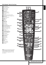
9. If you have a camcorder, video game or other
audio/video device that is connected to the AVR
on a temporary, rather than permanent basis,
connect the audio, video and digital audio out-
puts of that device to the Front Panel Inputs
*ÓÔ
. A device connected to the Video 3
jacks
Ô
is selected as the Video 3 input, and
connected to the digital jacks
*Ó
it is
selected as "Optical 3" or "Coaxial 3" input.
(See page 18 for more information on input
configuration.)
10. Connect the AVR to your video display using
one of the following connections, even if you will
also use an HDMI connection: