


INSTALLATION AND CONNECTIONS 13
ENGLISH
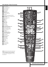
Installation and Connections
After unpacking the unit, and placing it on a solid
surface capable of supporting its weight, you will
need to make the connections to your audio and
video equipment.
Audio Equipment Connections
We recommend that you use high-quality inter-
connect cables when making connections to
source equipment and recorders to preserve the
integrity of the signals.
When making connections to audio source
equipment or speakers it is always a good
practice to unplug the unit from the AC wall
outlet. This prevents any possibility of
accidentally sending audio or transient signals to
the speakers that may damage them.
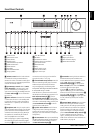
1. Connect the analog output of a CD player to
the CD inputs
6
.
NOTE: When the CD player has both fixed and
variable audio outputs it is best to use the fixed
output unless you find that the input to the
receiver is so low that the sound is noisy, or so
high that the signal is distorted.
2. Connect the analog Play/Out jacks of a
cassette deck, MD, CD-R or other audio recorder
to the Tape Input jacks
2
. Connect the analog
Record/In jacks on the recorder to the Tape
Output jacks
3
on the AVR.
3. Connect the digital output of any digital
sources such as a CD or DVD changer or player,
advanced video game, a digital satellite receiver,
HDTV tuner or digital cable set-top box or the
output of a compatible computer sound card to
the Optical and Coaxial Digital Inputs
RN*Ó
.
We recommend connecting the coaxial digital
audio output of your DVD player to the Coax 1
Digital Audio Input
N
, since that digital input
is assigned to the DVD source by default.
The Video 2/Cable/Sat source defaults to the
Optical 1 Digital Audio Input
R
. If your
cable television set-top box or satellite receiver is
equipped with an optical digital audio output,
we recommend that you connect it to this input
to obtain the benefits of higher-quality digital
audio (such as PCM, Dolby Digital 2.0 or Dolby
Digital 5.1 signals when broadcast by your cable
or satellite provider).
4. Connect the Coaxial or Optical Digital
Outputs
A
on the rear panel of the AVR to the
matching digital input connections on a CD-R or
MiniDisc recorder.
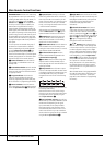
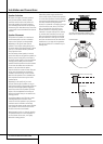
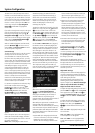
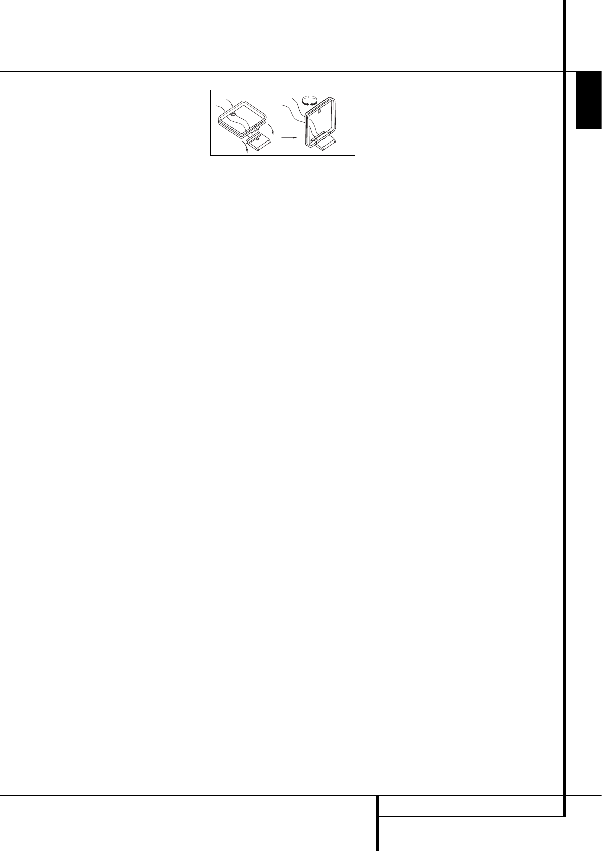
5. Assemble the AM Loop Antenna supplied with
the unit as shown below. Connect it to the AM
and GND screw terminals
0
.
6. Connect the supplied FM antenna to the FM
(75 ohm) connection
1
. The FM antenna may
be an external roof antenna, an inside powered
or wire lead antenna or a connection from a
cable system. Note that if the antenna or
connection uses 300-ohm twin-lead cable, you
should use a 300-ohm-to-75-ohm adapter to
make the connection.
7. Connect an MP3 player, iPod or portable CD to
the Aux In minijack audio input to listen to music
through the AVR 155. Usually the headphone
jack on the portable player is the only one that
can be used, and you have to adjust the volume
to be at a reasonable level on the portable unit
as well as on the AVR 155. If a fixed Line Out
jack or dual phono plug output jacks are avail-
able, using these with the proper cables may
result in better sound quality.
8. Connect the front, center and surround
speaker outputs
DEF
to the respective
speakers.
To assure that all the audio signals are carried to
your speakers without loss of clarity or resolution,
we suggest that you use high-quality speaker
cable. Many brands of cable are available and the
choice of cable may be influenced by the distance
between your speakers and the receiver, the type
of speakers you use, personal preferences and
other factors. Your dealer or installer is a valuable
resource to consult in selecting the proper cable.
Regardless of the brand of cable selected, we re-
commend that you use a cable constructed of fine,
multistrand copper with an area greater than 2 mm
2
.
Cable with an area of 1.5 mm
2
may be used for
short runs of less than 4 m. We do not recom-
mend that you use cables with an area less than
1mm
2
due to the power loss and degradation in
per for mance that will occur.
Cables that are run inside walls should have the
appropriate markings to indicate listing with any
appropriate testing agency standards. Questions
about running cables inside walls should be
referred to your installer or a licensed electrician
who is familiar with the applicable local building
codes in your area.
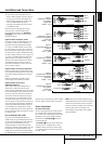
When connecting wires to the speakers, be
certain to observe proper polarity. Note that the
positive (+) terminal of each speaker connection
now carries a specific color code as noted on
page 8. However, most speakers will still use a
red terminal for the postive (+) connection.
Connect the “negative” or “black” wire to the
same terminal on both the receiver and the
speaker.
NOTE: While most speaker manufacturers
adhere to an industry convention of using black
terminals for negative and red ones for positive,
some manufacturers may vary from this con -
figura tion. To assure proper phase and optimal
performance, consult the identification plate on
your speaker or the speaker’s manual to verify
polarity. If you do not know the polarity of your
speaker, ask your dealer for advice before pro-
ceeding, or consult the speaker’s manufacturer.
We also recommend that the length of cable
used to connect speaker pairs be identical. For
example, use the same length piece of cable to
connect the front-left and front-right or
surround-left and surround-right speakers, even
if the speakers are a different distance from the
AVR.
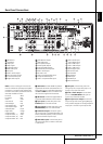
9. Connections to a subwoofer are normally
made via a line level audio connection from the
Subwoofer Output
4
to the line-level input
of a subwoofer with a built-in amplifier. When a
passive subwoofer is used, the connection first
goes to a power amplifier, which will be
connected to one or more subwoofer speakers. If
you are using a powered subwoofer that does
not have line-level input connections, follow the
instructions furnished with the speaker for
connection information.
10. If an external multi-channel audio source
with 5.1 outputs such as an external digital
processor/decoder, DVD-Audio or SACD player is
used, connect the outputs of that device to the
6-Channel Direct Inputs
9
.
Video Equipment Connections
Video equipment is connected in the same manner
as audio components. Again, the use of high-
quality interconnect cables is recommended to
preserve signal quality. To ensure best video per-
formance S-Video sources should be connected
to the AVR only with their S-Video In/Outputs,
not with their composite video connectors too.
1. Connect a VCR’s audio and video Play/Out
jacks to the Video 2 In jacks
MO
on the rear
panel. The Audio and Video Record/In jacks on
the VCR should be connected to the Video 1
Out jacks
P7
on the AVR.
2. Although any video device may be connected
to these jacks, we recommend connecting your
TV to the Audio 1 Audio/Video Input Jacks
HQ
so that you may take advantage of the fact
that the remote control is preprogrammed with
TV product codes for the Video 1 device.
For the same reason, we recommend connecting
your video recorder, cable TV converter or
satellite receiver to the Video 2 Audio/Video
Input Jacks
MO
.
3. Connect the analog audio and video
outputs of a DVD or laser disc player to the
DVD jacks
5C
.