


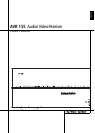
6 FRONT PANEL CONTROLS
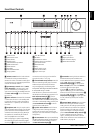
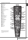
Front Panel Controls
)
Tuning Selector: Press the left side of the
button to tune lower frequency stations and the
right side of the button to tune higher frequency
stations. When a station with a strong signal is
reached,
MANUAL TUNED or AUTO
TUNED will appear in the Main Information
Display
Ò
(see page 41 for more information
on tuning stations).
!
Tuner Band Selector: Pressing this button
will automatically switch the AVR to the Tuner
mode. Pressing it again will switch between the
AM and FM frequency bands, holding it pressed
for some seconds will switch between stereo and
mono receiving and between automatic and
manual tuning mode (See page 41 for more
information on the tuner).
@ OK Button: When making choices during the
setup and configuration process, press this button
to enter the desired setting as shown in the
Main Information Display
Ò
into the AVR’s
memory.
#
Preset Stations Selector: Press this
button to scroll up or down through the list of
stations that have been entered into the preset
memory (See page 41 for more information on
tuner programming).
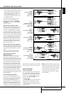
$
Speaker/Channel Input Indicators:These
indicators are multipurpose, indicating either the
speaker type selected for each channel or the
incoming data-signal configuration. The left, center,
right, right surround and left surround speaker
indicators are composed of three boxes, while the
subwoofer is a single box. The center box lights
when a “Small” speaker is selected, and the two
outer boxes light when “Large” speakers are
selected. When none of the boxes are lit for the
center, surround or subwoofer channels, no speaker
has been selected for that position. (See page 23
for more information on configuring speakers.) The
letters inside each of the center boxes display
active input channels. For standard analog inputs,
only the L and R will light, indicating a stereo
input. When a digital source is playing, the indica-
tors will light to display the channels begin
received at the digital input. When the letters
flash, the digital input has been interrupted.
(See page 35 for more information on the Channel
Indicators).
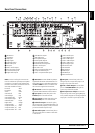
%
Input Source Selector: Press this button to
change the input by scrolling through the list of
input sources.
^
RDS Select Button: Press this button to
display the various messages that are part of the
RDS data system of the AVR’s tuner.
(See page 42 for more information on RDS).
&
Delay: Press this button to begin the
sequence of steps required to enter delay time
settings (See page 26 for more information on
delay times).
*
Digital Optical 3 Input: Connect the optical
digital audio output of an audio or video product
to this jack. The Input is protected by a spring-acti-
vated closing flap, which opens when you insert
an optical (TOS) plug and closes again when you
remove it. You may hide this input and the one
next to it with the supplied trim panel..
(
Channel Select Button: Press this button
to begin the process of trimming the channel
output levels using an external audio source.
(For more information on output level trim
adjustment, see page 37).
Ó
Digital Coax 3 Input: This jack is normally
used for connection to the output of portable
digital audio devices, video game consoles or
other products that have a coax digital jack.
Ô
Video 3 Input Jacks: These audio/video
jacks may be used for temporary connection to
video games or portable audio/video products
such as camcorders and portable audio players.
Digital Input: When playing a source that
has a digital output, press this button to select
between the Optical (28) and Coaxial (24)
digital inputs. (See pages 17 and 33 for more
information on digital audio).
Ò
Main Information Display: This display
delivers messages and status indications to help
you operate the receiver.
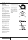
Ú
Remote Sensor Window: The sensor
behind this window receives infrared signals from
the remote control. Aim the remote at this area
and do not block or cover it unless an external
remote sensor is installed.